background image


3. Description and Operation


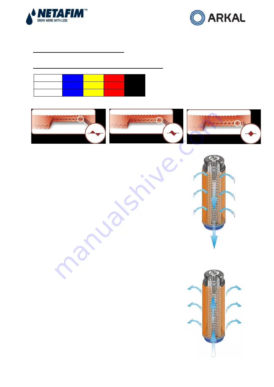
Table of Filtration Grades of the Discs and Color Code


Color Code


Blue


Yellow


Red


Black


Mesh


40


80


120


140


Micron


400


200


130


100


Spin Klin Spine - The Core of the Spin Klin Filtration System


The  Spin  Klin

®  

discs  are  stacked  on  the  Spin  Klin

®  

spine.  The 

discs   are   color-coded   according   to   micron   size,   and   are 

assembled  to  suit  your  water  filtration  requirements.  The  spine 

assembly  has  a  spring  compression  unit  and  an  internal  piston, 

which  operate  during  alternate  filtration  or  backwash modes.  The 

spine  assembly  is  specially  designed  to  compress  the  micron 

housing.  Inside  the  housing  a  spring  and  the  pressure  difference 

compress the discs tightly  during the  filtration process, forcing the 

water to flow between the grooves and trap the solids. 


Spin Klin Automatic Backwash Operation


Activated  by  a  predefined  command  (differential  pressure  or 

time)  alternate units  of  the  Spin  Klin

® 

system  go  into  backwash 

mode. The inlet valve is shut as the drain is automatically opened. 

During  the  backwash  process,  the  compression  spring  is 

released and the pressure difference is eliminated. The spine 

piston  rises  up,  releasing the  pressure  on  the  discs.  Tangential 

jets  of  clean water are pumped at  high pressure in  the opposite 

direction  through  nozzles  at  the  center  of  the  spine.  The  discs 

spin  free  and  clear,  loosening  the  trapped  solids.  Solids  are 

quickly and efficiently flushed out through the drain. 

Содержание Spin Klin Angle Apollo 3"

Страница 1: ...2 3 4 Apollo SK 910101 000594 08 2013 ENG 3 Spin Klin Angle Apollo Battery Service Maintenance Manual ...

Страница 2: ...of Contents Subject Page No 1 Introduction 3 2 Safety Instructions 3 3 Description and Operation 4 4 Technical Data 6 5 Headloss Chart 6 6 P ID 7 7 System Maintenance 8 8 Troubleshooting 13 Limited Warranty 15 ...

Страница 3: ...draining prior to service 2 Take precautions while lifting transporting or installing the filter 3 Installation of the filter should be performed so as to avoid direct water splashing on any of the filter parts and especially on the electronic control unit 4 Confirm that filter weight when full meets the support construction requirements 5 Prior to installation confirm that line pressure matches f...

Страница 4: ...ing a spring and the pressure difference compress the discs tightly during the filtration process forcing the water to flow between the grooves and trap the solids Spin Klin Automatic Backwash Operation Activated by a predefined command differential pressure or time alternate units of the Spin Klin system go into backwash mode The inlet valve is shut as the drain is automatically opened During the...

Страница 5: ... to the drain The filtered backwash water is supplied from the other filters through the outlet manifold The contaminated water from the backwashed filter drains through the drainage manifold Backwash time per filter is between 20 25 seconds When the time elapses the control unit stops the backwash signal to the solenoid The solenoid releases the water pressure signal allowing the inlet valve and ...

Страница 6: ...7 4 Technical Data 3 Spin Klin Angle Apollo Depended on the water quality 5 Batteries Headloss Chart 130 micron 3 Spin Klin Angle Apollo s ...

Страница 7: ... automatic Check that the P hydraulic switch HIGH and LOW pressure lines are correctly connected to the appropriate ports Set the starting backwash switch to P 5 7 meters 6 8 psi Set the controller to a flush time of 20 25 seconds and a dwell time of 10 seconds These settings may require adjustment to conform to local water conditions Typically a 1 to 3 hour interval between backwashes is recommen...

Страница 8: ...sh controller performance Check that the controller timing parameters are correctly adjusted and activate automatic backwash cycle In the event of possible failure at the backwash controller check for possible failures Cleaning of the Command Filter Close the command filter inlet valve Release the static pressure by opening the drain valve Remove the cover Thoroughly clean the filter element and t...

Страница 9: ... a cleaning solutions HCL Chlorine or other refer to Cleaning Recommendations Clogged Filtration Discs Figure 6 Ensure that the correct quantities of discs are assembled on the spines when the discs are pressed with two hands the top disc should be level with the imprinted circle on the outside of the spine Figure 7 Figure 1 Figure 2 Figure 3 Figure 4 Figure 5 Figure 6 Tighten the butterfly nut un...

Страница 10: ...the cover easily you should drain the water from the filter You may drain the filter through the drain valve located on the filter body once the filter is empty the cover can then be removed safely and easily Cleaning Recommendations for Clogged Filtration Discs Water formed deposits may cause clogging of the filter discs The formation of these deposits depends on the quality of the filtered water...

Страница 11: ...ated area Follow the manufacturer s instructions Cleaning Organic and Biological Deposits Open the filter and remove dirty discs Attention Never open the filter before the pressure has been released Arrange the discs loosely on the plastic rope Prepare a 5 Sodium Hypochlorite solution 1 Pour 5 liters of water into one of the large containers 2 Add 5 liters of Sodium Hypochlorite 10 into the water ...

Страница 12: ...t is not known perform the following test Take 5 discs for the test Soak 2 discs in a 5 Sodium Hypochlorite Solution Preparation of the solution Pour 1 cup of water into a small container then add 1 cup of Sodium Hypochlorite 10 NaOCl Soak 2 discs in a 5 Hydrochloric Acid Solution Preparation of the solution Pour 2 cups 500ml of water into a small container then add carefully cup 100ml of Hydrochl...

Страница 13: ...source Replace battery if needed Check solenoid electrical connectors Repair or replace the solenoid Check the booster valve Command not received Functioning correctly Receives command Check the 8mm command tube Repair or replace the booster valve if needed Check the valves Command not received Receives command Check the water supply control tube Remove the valve s cover Check the diaphragm and th...

Страница 14: ...bed above Contact your local distributor Command transfer No command transfer Disconnect the drain manifold Check controller No command transfer Command transfer Replace control panel Check the solenoid No command transfer Command transfer Replace the solenoid if needed Check the booster valve No command transfer Command transfer Replace the booster valve if needed Contact your local distributor L...

Страница 15: ...enses of any kind or nature regardless of the nature thereof including without limitation injury to persons or property loss of use of the products loss of goodwill loss of profits or any other contingent liabilities of any kind or character alleged to be the cause of loss or damage to the purchaser This warranty does not cover damage or failure caused by misuse abuse or negligence nor shall it ap...

Отзывы: