8
1.4
S
ERVICING AND
R
EMOVAL
OF THE
G
AS
V
ALVE
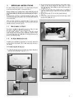
1.4.1 Setting the gas pressures
1
2
3
4
A
B
C
F
G
D
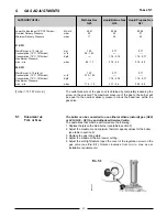
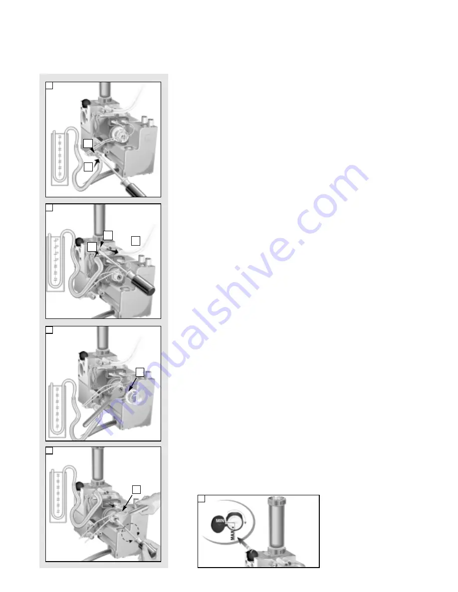
Setting the minimum and the maximum power of the boiler
1. Check that the supply pressure to the gas valve is a minimum of 20 mbar
for natural gas. Turn off the gas supply at the isolation point under the
boiler
2. To do this, slacken the screw “A”.
Fit the pipe of the pressure gauge to the inlet pressure test point of the gas
valve “B”.
Turn on the gas supply at the isolation point under the boiler and with
the boiler running, read the inlet working pressure on the gauge.
When you have completed this operation, turn off the gas supply at the
isolation point under the boiler, remove the pressure gauge and tighten
the screw “A” securely into its housing to seal off the gas. Turn on the gas
supply at the isolation point under the boiler and test the screw for
gas escaping with an approved soap and water solution.
3. To check the pressure supplied by the gas valve to the burner, with the
boiler turned off, slacken the screw “C”. Fit the pipe of the pressure gauge
to the outlet pressure test point of the gas valve “D”.
Disconnect the compensation pipe “E”either from the gas valve or from
the sealed chamber.
4. Push the On/Off button to “ON” position -green light- and push the Heating
button to “ON” position -green light-
Turn on the boiler by setting the external controls.
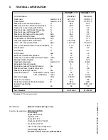
Adjust the 10mm nut “F” on the modureg to set the gas pressure Turn the
nut clockwise to increase and anti clockwise to decrease the pressure until
the required pressure is achieved (see T
ABLE
A page 9)
5. To set the minimum power, disconnect the supply cable from the modureg
and adjust screw “G” whilst holding nut “F”.
Turn the screw clockwise to increase the pressure and anticlockwise to
decrease the pressure until the required pressure is achieved (see T
ABLE
A page 9)
6. When you have completed the above operations, turn off the external
controls, re-connect the supply terminal to the modureg on the gas valve
and replace the cap on the screw of the modureg.
Setting pressure for soft ignition.
The soft light pressure is factory set.
If the ignition is not regular (e.g: not complete burner ignition or ignition
noise) check the soft light regulator position.
The soft light pressure will need adjusting as follows:
- Turn off electrical supply;
- referring to diagram 5, open the dust cap of the soft light regulator, by
unscrewing in clockwise direction the white screw;
- turn the adjustment screw one step in the direction max to increase or in
the direction min to decrease the soft light pressure;
- after each adjustment of the regulator, turn on the electrical supply and
recheck burner ignition (wait 20 seconds between each cycle to allow
the gas valves’ internal servo system to reset). When the required level
is achieved, close the dust cap.
7. Remove the pipe from the pressure gauge and connect screw “C” to the
pressure outlet in order to seal off the gas.
8. Carefully check the pressure outlets for gas leaks (valve inlet and outlet).
IMPORTANT!
Whenever you disassemble
and reassemble the gas
connections, always check for
leaks using an approved soap
and water solution.
VG002Ac
VG002Ad
VG002Af
VG002Ae
E
V
G002Ab
5


