Cabling the Switch
4.4
Connecting Serial and Management Cables
This section discusses the serial and management cables requirements and connections.
The accessory kit includes the following cables:
•
RJ-45 to DB-9 serial adapter cable.
•
RJ-45 Ethernet cable.
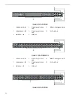
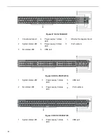
Either the front panel or the rear panel has the console, management, and USB ports.
display the front and rear panels of all switches covered by this guide.
Table 6: RJ-45 to DB-9 Connections
lists the pin connections of the RJ-45 to DB-9 adapter cable.
Table 6: RJ-45 to DB-9 Connections
RJ-45
DB-9
RJ-45
DB-9
RTS
1
8
CTS
GND
5
5
GND
DTR
2
6
DSR
RXD
6
3
TXD
TXD
3
2
RXD
DSR
7
4
DTR
GND
4
5
GND
CTS
8
7
RTS
Note: RJ-45 to DB-9 connections: For models with a console management port on the rear
panel, RJ-45 pin 1 (RTS) is connected to RJ-45 pin 8 (CTS); RJ-45 pin 2 (DTR) and RJ-45 pin
7 (DSR) are not electrically connected to any signal.
Figure 22: Console, Management, and USB Ports
displays the console, management, and USB ports
in a representative configuration. Some earlier devices have ports where the USB port is located
slightly differently.
Figure 22: Console, Management, and USB Ports
1
System status LED
3
Activity status LED
5
USB port
2
Ethernet management
port
4
Serial console port
6
Link status LED
23


