


Operating_Instructions_RPE3-062x/xS3_14087_1en_05/2022
Page 13
www.argo-hytos.com
Normal operation of the system does not require any manipulation of the valve. The valve spool is adjusted by the control unit signal via the control
solenoid. The position sensor checks that the set position has been reached and sends a double feedback signal to the control unit.
6.4 Normal operation
DO NOT EXCEED THE MAXIMUM PARAMETERS
, shown in table 3.3.
OBSERVE OPERATING RESTRICTIONS AND AVOID RISKS
, referred to in paragraph 2.
USE PROTECTIVE EQUIPMENT
When working with hydraulic fluid, it is recommended to wear safety goggles, protective rubber gloves and sturdy shoes with non-slip soles.
If the power supply to the hydraulic system fails and the pressure drops,
the spool position will not change.
In the event of a power failure
the centering spring will return the valve spool to its base position. If you need to reposition the valve spool in
an emergency, e.g. to reach a safe position of the mechanism,
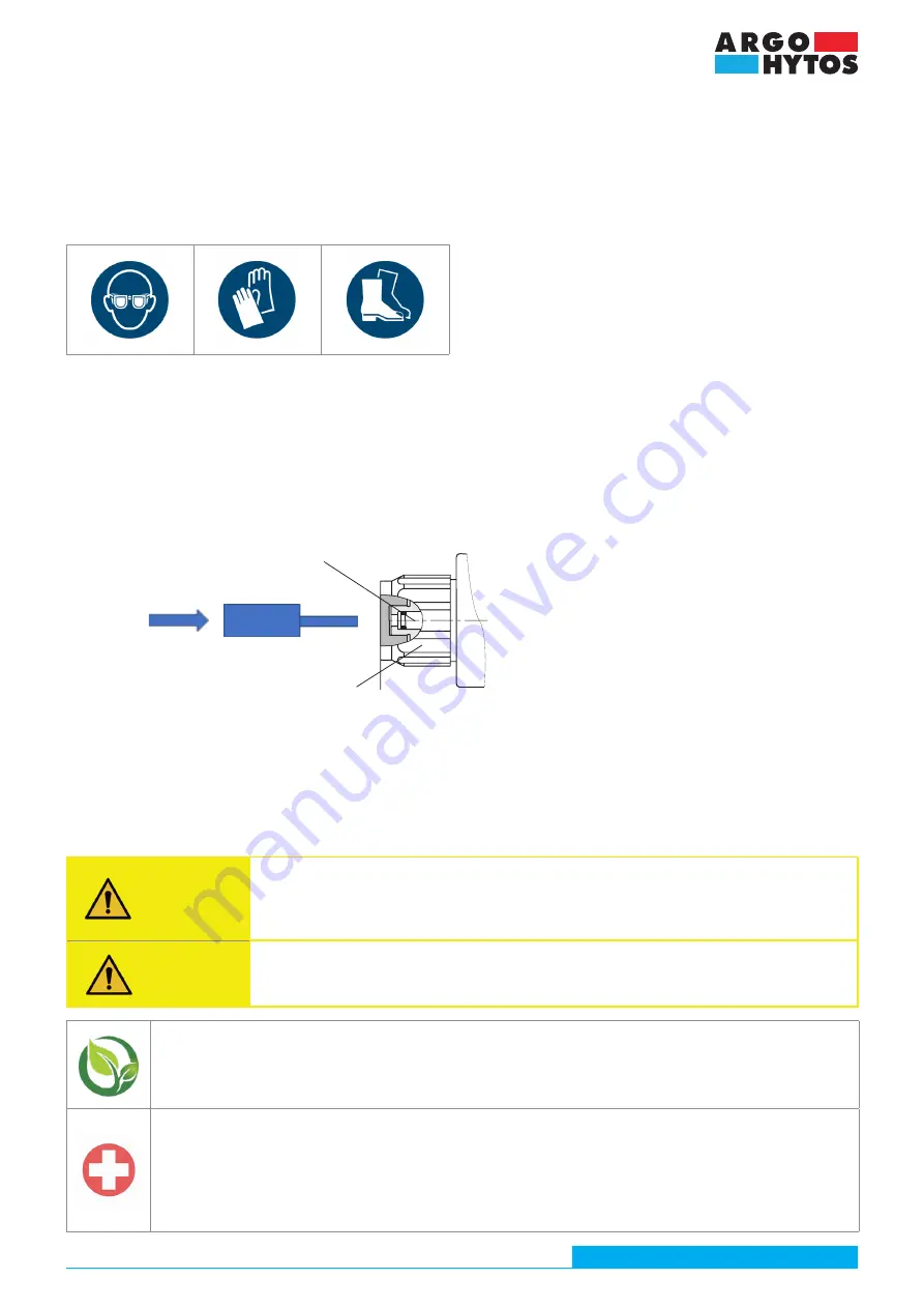
use the manual override
, built into the plug of the solenoid control system:
› Remove the plastic retaining nut that covers the manual override pin by turning it counterclockwise.
› Insert the pin, with a diameter d ≤ 3.3 mm and sufficient hardness, into the hole in the plug. The spool can be moved to the working position
by applying pressure. However, manual repositioning of the spool is only possible up to a pressure of 25 bar in the T-channel.
› When manual override is complete, rotate the spool to the desired position and secure the spool by tightening the plastic nut clockwise with
a tightening torque of 3+1 Nm.
6.5 Exceptional and emergency situations
WARNING
Pressure source shutdown and circuit relief
In the event of an emergency, turn off the pressure source (pump) and relieve all parts of the hydraulic circuit
including the hydraulic accumulators, relieve them by connecting them to the tank. Always ensure that the circuit
is depressurised before intervening in the circuit, for example by removing a valve. Otherwise there is a risk of
leakage of working fluid and contamination of persons.
WARNING
Disconnecting the power supply
Disconnect the electrical parts of the valve from the power supply. There is a risk of electric shock and unintentio-
nal activation of the valve can lead to serious situations.
ENVIRONMENTAL PROTECTION
Spilled working fluid must be removed immediately, e.g. with suitable absorbents, contaminated parts of the perimeter cleaned,
contaminated objects in the vicinity cleaned or disposed of.
Contaminated objects and residues of leaked working fluid must be disposed of in accordance with the applicable environmental
regulations.
FIRST AID
If persons become contaminated, contaminated clothing must be removed immediately and the skin thoroughly washed with soap
or treated with a suitable cream.
If the eyes are contaminated, flush them with clean water and seek medical attention. Seek medical attention also in case of
accidental ingestion of working fluid or skin allergic reaction to splashes of working fluid.
In
the event of an electric shock
immediately switch off the power source, call for emergency medical assistance and, if possible,
start resuscitation if the victim has fallen unconscious and is not breathing (CPR, use of a defibrillator, etc.).
79,5 (3.13)
a
Based on the results of the risk analysis, three potential defects were identified:
› External valve leakage due to seal damage associated with a working fluid leak. If a leak is detected in the dividing plane between the valve and
the connection plate, the fault can be rectified by replacing the sealing rings. Replace the leaking valve between the body and the control system/
sensor extension with a new one and send the defective one to the manufacturer for repair.
› The spool does not move due to a defective coil. First check that the coil is actually powered (no damage to the cable, controller or connector). You
can replace the defective coil with a new working one after loosening the plastic nut.
› The position sensor does not give any signal to the control unit about the spool position. First check that the position sensor is correctly
connected (no damage to the cable, control unit or connector). A valve with a malfunctioning position sensor must be replaced.
emergeny manual override pin
Plastic nut (3+1 Nm)


