
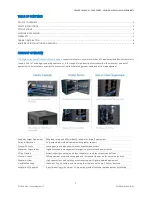


OWNER’S MANUAL: EDGE
-SERIES
–
SWING GATE WALL MOUNT CABINETS
7
© 2018 ArcTiv Technologies, LLC
ATSGWM-MANUAL-01
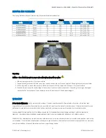
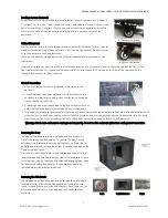
Installing Castors (Optional)
An optional castor kit (not included) may be installed for each cabinet which includes 4,
2” castors
- 2 with brake. The kit includes 4 casters with required locknuts, washers and
bolts for installation. Using two 10 mm open-end or combination wrenches, install the
casters to the base of the unit using the pre-drilled holes near each corner of the
enclosure.
2” Castor wi
th Brake
Cabinet Placement
You can use the casters to move the enclosure for a short distance over a level, smooth,
stable surface by pushing it from the front or rear (not the side panels). Do not attempt
to roll the enclosure over long distances.
Warning: Use appropriate equipment and follow all applicable safety procedures and
regulations.
2” Castor w/o Brake
After the enclosure has been moved to the installation location, use a carpenter's level to check the slope of the floor. If the
floor slopes more than 1%, choose an alternate installation site. Locate the 2 castors on the front of the cabinet with the
locking brake and secure them into place.
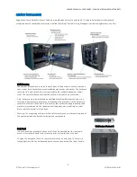
Ground Connection
•
All parts of the enclosure are grounded to the frame of the
enclosure.
•
Grounding studs have been provided in all four corners of the
enclosure to allow for grounding in any configuration (including
front or back door reversals).
•
Grounding holes are also provided on top and bottom corners of
both front and back doors to accommodate any configuration.
•
To ground the enclosure simply connect the two quick-disconnect grounding wires, one to the hole provided on the inside of
either the front or back door and the other to the stud provided in any corner of the enclosure. Connect your fa
cility’s earth
ground connection to the grounding stud not used by door connections, using an 8 AWG (3.264 mm) wire.
Warning: Attach each enclosure to earth ground separately. Do not use the enclosure without an earth ground connection.
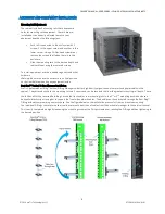
Reversing the Door
The door of the enclosure is
held in position on the enclosure’s
frame with two spring-
loaded pins. To reverse the door’s swing
direction, simply release the pins by pulling them up (lower pin) or
down (upper pin) and remove them from the mounting holes on the
frame of the enclosure.
Flip the door in the opposite direction and replace the pins in the
identical mounting holes on the ot
her side of the enclosure’s frame
by lining them up with the mounting holes and engaging them again.
For doors with swing-lock handles, the handle will need to be
removed via a screwdriver and reversed.
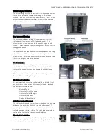
Removing the Side Panels
The side panels include a key lock and quick release on all models
(vented or solid). Remove the side panel by unlocking the small
round lock and pressing on the quick releases. Once removed, this
will provide open access to the equipment and cables for easy
servicing.
Lock
Quick Release
Keys


