


5-8
3. With the selector switch in the 2WD position, the
meter must show less than 1 ohm.
4. With the selector switch in the 4WD position, the
meter must show an open circuit.
NOTE: If the meter does not show as specified,
replace the front drive selector switch.
VOLTAGE
NOTE: The battery must be connected when per-
forming voltage tests.
1. Set the meter selector to the DC Voltage position.
2. Connect the black tester lead to the negative bat-
tery terminal.
3. Connect the red tester lead to the brown/lavender
wire on the harness side of the connector.
4. Turn the ignition switch to the RUN position.
5. The meter must show battery voltage.
NOTE: If the meter shows other than specified,
check the harness, connector, 30 amp fuse, and
battery connections.
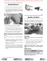
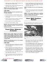
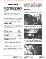
Front Drive Selector
Actuator
NOTE: With the engine stopped and the ignition
switch in the ON position, a momentary “whirring”
sound must be noticeable each time the selector
switch is moved to 2WD and 4WD. Test the switch,
30 amp fuse, and wiring connections prior to test-
ing the actuator.
NOTE: The differential must be in the unlocked
position for this procedure.
VOLTAGE
1. Select the 2WD position on the front drive selector
switch; then disconnect the connector on the actu-
ator wiring harness.
2. With the ignition switch in the OFF position, con-
nect the black tester lead to the black wire in the
supply harness; then connect the red tester lead to
the brown/lavender wire in the supply harness.
3. Turn the ignition switch to the ON position. The
meter must show 12 DC volts.
4. Connect the red tester lead to the white/blue wire
in the supply harness. The meter must show 12 DC
volts.
5. Select the 4WD position on the front drive selector
switch; then connect the red tester lead to the
white/blue wire in the supply harness. The meter
must show 0 DC volts.
NOTE: The 4WD icon on the LCD should illumi-
nate.
6. Connect the red tester lead to the brown/lavender
wire in the supply harness. The meter must show
12 DC volts.
NOTE: If the voltage readings are as specified
and the actuator does not function correctly,
replace the actuator (see Section 6).
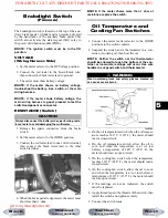
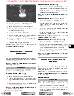
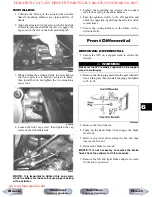
Gear Shift Position
Switch
The gear shift position switch connector is located on
the right side of the engine over the V-belt housing.
KC227A
To troubleshoot the switch, use the following proce-
dure.
1. Disconnect the gear shift position switch from the
main harness at the connector; then connect the
black tester lead to a suitable ground.
2. Select the OHMS position on the tester and con-
nect the red tester lead to the lavender/red wire;
then move the gear shift lever to the R (reverse)
position. The meter must read less than 1 ohm.
3. Move the red tester lead and shift lever in turn to
the light green/red wire and N (neutral) position,
white/black wire and H (high) position, and
white/red wire and L (low) position. The meter
must read less then 1 ohm in all positions. If not,
the gear shift linkage must be adjusted (see Sec-
tion 2) or the switch must be replaced.
Next
Back
Section
Table of Contents
Manual
Table of Contents
FOR ARCTIC CAT ATV DISCOUNT PARTS CALL 606-678-9623 OR 606-561-4983
www.mymowerparts.com


