


2-6
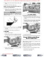
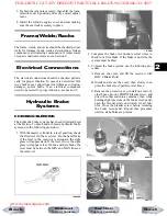
CHECKING AND CLEANING DRAIN
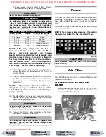
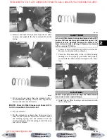
1. Inspect the drain on the filter housing cover and
clean out any dirt or debris.
KC0056C
2. Replace any drain that is cracked or shows any
signs of hardening or deterioration.
3. Wipe any accumulation of oil or gas from the filter
housing and drain.
Valve/Tappet Clearance
(Feeler Gauge Procedure)
To check and adjust valve/tappet clearance, use the
following procedure.
NOTE: The seat, left-side and right-side engine
covers, and gas tank must be removed for this pro-
cedure.
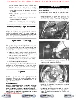
1. Remove the timing inspection plug and spark
plug; then remove the tappet covers (for more
detailed information, see Section 3 - Servicing
Top-Side Components).
2. Rotate the crankshaft to the TDC position on the
compression stroke.
NOTE: At this point, the rocker arms and adjuster
screws must not have pressure on them.
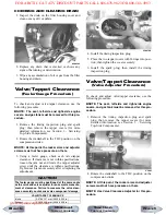
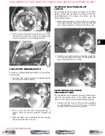
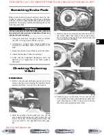
3. Using a feeler gauge, check each valve/tappet
clearance. If clearance is not within specifications,
loosen the jam nut and rotate the tappet adjuster
screw until the clearance is within specifications.
Tighten each jam nut securely after completing the
adjustment.
CC007DC
4. Install the timing inspection plug.
5. Place the two tappet covers with O-rings into posi-
tion; then tighten the covers securely.
6. Install the spark plug; then install the timing
inspection plug.
Valve/Tappet Clearance
(Valve Adjuster Procedure)
To check and adjust valve/tappet clearance, use the
following procedure.
NOTE: The seat, left-side and right-side engine
covers, and gas tank must be removed for this pro-
cedure.
1. Remove the timing inspection plug and spark
plug; then remove the tappet covers (for more
detailed information, see Section 3 - Servicing
Top-Side Components).
CF005
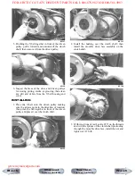
2. Rotate the crankshaft to the TDC position on the
compression stroke.
NOTE: At this point, the rocker arms and adjuster
screws must not have pressure on them.
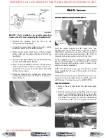
NOTE: Use Valve Clearance Adjuster for this pro-
cedure.
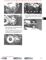
CAUTION
The feeler gauge must be positioned at the same angle
as the valve and valve adjuster for an accurate measure-
ment of clearance. Failure to measure the valve clear-
ance accurately could cause valve component damage.
VALVE/TAPPET CLEARANCE
Intake
0.076-0.127 mm (0.003-0.005 in.)
Exhaust
0.152-0.203 mm (0.006-0.008 in.)
Next
Back
Section
Table of Contents
Manual
Table of Contents
FOR ARCTIC CAT ATV DISCOUNT PARTS CALL 606-678-9623 OR 606-561-4983
www.mymowerparts.com


