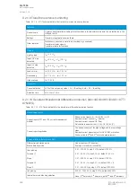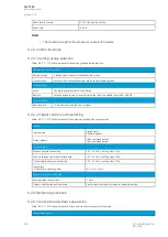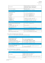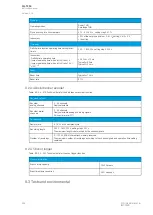
9.2.1.4 Harmonic overcurrent protection (Ih>; 50H/51H/68H)
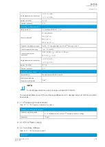
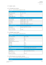
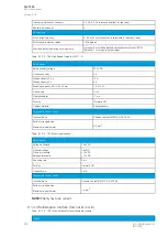
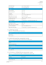
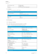
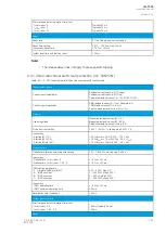
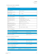
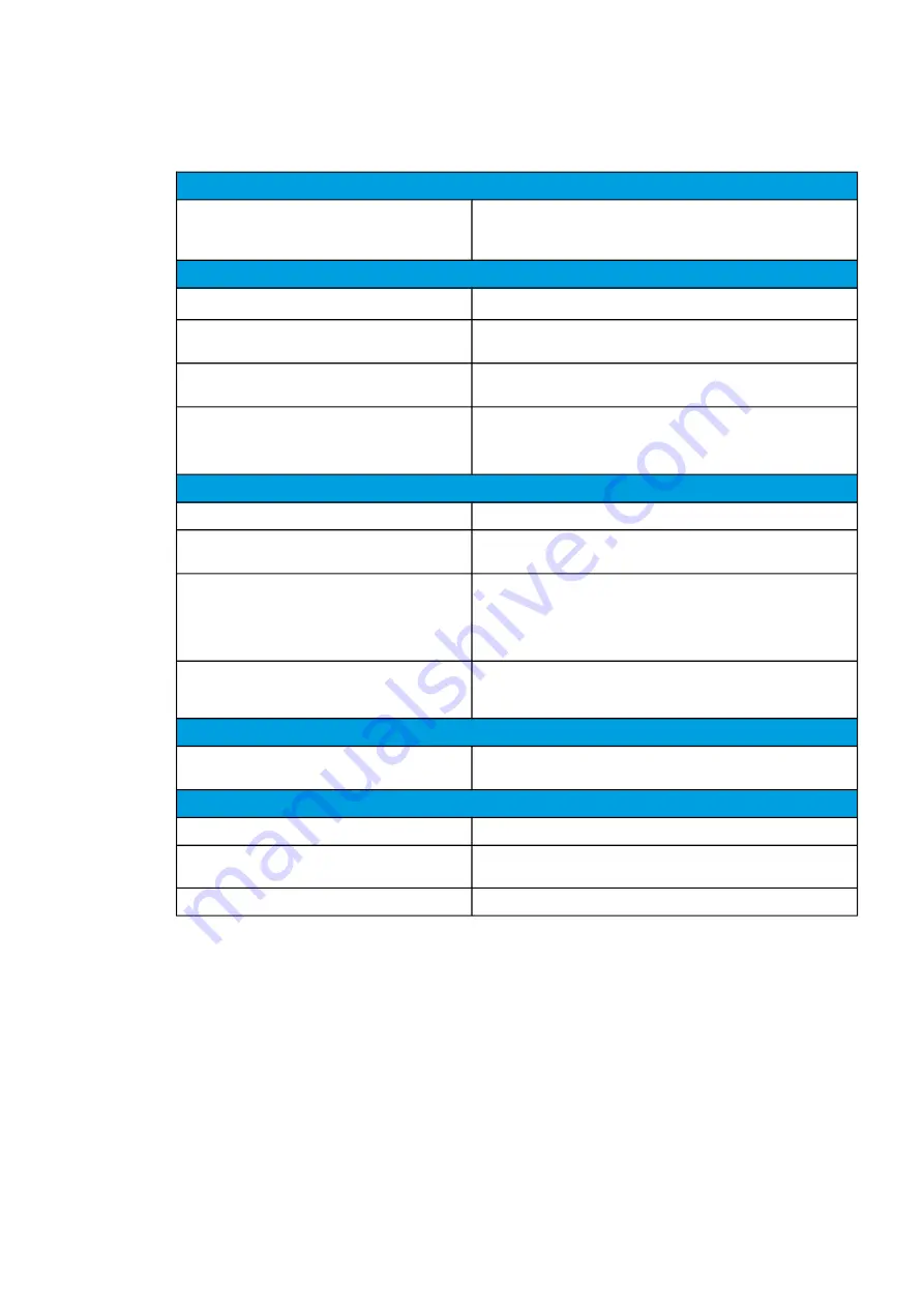
Table. 9.2.1.4 - 206. Technical data for the harmonic overcurrent function.
Measurement inputs
Current inputs
Phase current inputs: I
L1
(A), I
L2
(B), I
L3
(C)
Residual current channel I
01
(Coarse)
Residual current channel I
02
(Fine)
Pick-up
Harmonic selection
2
nd
, 3
rd
, 4
th
, 5
th
, 6
th
7
th
, 9
th
, 11
th
, 13
th
, 15
th
, 17
th
or 19
th
Used magnitude
Harmonic per unit (× I
N
)
Harmonic relative (Ih/IL)
Pick-up setting
0.05…2.00 × I
N
, setting step 0.01 × I
N
(× I
N
)
5.00…200.00 %, setting step 0.01 % (Ih/IL)
Inaccuracy:
- Starting × I
N
- Starting × Ih/IL
<0.03 × I
N
(2
nd
, 3
rd
, 5
th
)
<0.03 × I
N
tolerance to Ih (2
nd
, 3
rd
, 5
th
)
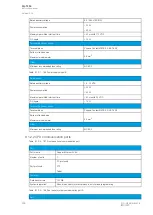
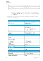
Operation time
Definite time function operating time setting
0.00…1800.00 s, setting step 0.005 s
Inaccuracy:
- Definite time (I
M
/I
SET
ratio >1.05)
±1.0 % or ±35 ms
IDMT setting parameters:
k Time dial setting for IDMT
A IDMT constant
B IDMT constant
C IDMT constant
0.01…25.00, step 0.01
0…250.0000, step 0.0001
0…5.0000, step 0.0001
0…250.0000, step 0.0001
Inaccuracy:
- IDMT operating time
- IDMT minimum operating time
±1.5 % or ±20 ms
±20 ms
Instant operation time
Start time and instant operation time (trip):
I
M
/I
SET
ratio >1.05
<50 ms
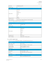
Reset
Reset ratio
95 % of the pick-up setting
Reset time setting
Inaccuracy: Reset time
0.010…10.000 s, step 0.005 s
±1.0 % or ±35 ms
Instant reset time and start-up reset
<50 ms
No
Notte!
e!
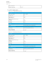
• Harmonics generally: The amplitude of the harmonic content has to be least 0.02 × I
N
when
the relative mode (Ih/IL) is used.
• Blocking: To achieve fast activation for blocking purposes with the harmonic
overcurrent stage, note that the harmonic stage may be activated by a rapid load change or
fault situation. An intentional activation lasts for approximately 20 ms if a harmonic
component is not present. The harmonic stage stays active if the harmonic content is above
the pick-up limit.
• Tripping: When using the harmonic overcurrent stage for tripping, please ensure that the
operation time is set to 20 ms (DT) or longer to avoid nuisance tripping caused by the above-
mentioned reasons.
A
AQ
Q-T256
-T256
Instruction manual
Version: 2.06
© Arcteq Relays Ltd
IM00028
295
Содержание AQ-T256
Страница 1: ...AQ T256 Transformer protection IED Instruction manual...
Страница 2: ......
Страница 264: ...Figure 7 3 120 Example block scheme A AQ Q T256 T256 Instruction manual Version 2 06 262 Arcteq Relays Ltd IM00028...
Страница 284: ...Figure 8 13 141 Device installation A AQ Q T256 T256 Instruction manual Version 2 06 282 Arcteq Relays Ltd IM00028...

