background image

7-20

SET-UP AND SAFE OPERATING PROCEDURES

89210000

NOTE

If you want a groove depth that is greater than 1-1/2 times the diameter of the 

electrode being used, make the groove in two or more passes.

Assembly And Installation

Содержание N6000 Automatic System

Страница 1: ...Issue Date October 1 2007 Manual No 89210000 Safety and Operating Instructions N6000 Automatic System English Français Español ...

Страница 2: ...ill help you to avoid potential hazards that may exist when working with this product YOU ARE IN GOOD COMPANY The Brand of Choice for Contractors and Fabricators Worldwide Arcair is a Global Brand of Carbon Arc Gouging Products for Thermadyne Industries Inc We manufacture and supply to major welding industry sectors worldwide including Manufacturing Construction Mining Automotive Aerospace Enginee...

Страница 3: ...Rd Denton TX 76208 940 566 2000 www thermadyne com U S Customer Care 800 426 1888 International Customer Care 905 827 9777 Copyright 2007 Thermadyne Industries Inc All rights reserved Reproduction of this work in whole or in part without written permission of the publisher is prohibited The publisher does not assume and hereby disclaims any liability to any party for any loss or damage caused by a...

Страница 4: ...DIAMETER 5 14 KEEPING ELECTRODES DRY 5 14 POWER SOURCES SUPPLIED BY USER FOR THE N6000 SYSTEM 5 14 SECONDARY POWER CABLES WELDING LEADS 5 15 COMPRESSED AIR 5 16 MAIN AIR LINE 5 16 SECTION 6 ASSEMBLY AND INSTALLATION 6 17 RECEIVING AND HANDLING 6 17 INSTALLING THE N6000 SYSTEM 6 17 CONNECTING STEPS 6 17 SECTION 7 OPERATING THE N6000 SYSTEM 7 21 CHANGING MODE OF OPERATION CC or CP 7 21 STARTING COND...

Страница 5: ...RICATED GIRDERS 9 30 SECTION 9 ARCAIR TITAN MACHINE CARRIAGE 9 31 GENERAL 9 31 POWER 9 31 CONTROL PANEL 9 31 TITAN SETUP AND ASSEMBLY 9 32 SECTION 10 ARCAIR CLIMBER V A TRAVEL SYSTEM 10 34 SECTION 11 TROUBLE SHOOTING GUIDE 11 38 N6000 Automatic System 11 38 CLIMBER V A TRACTOR 11 43 TITAN MACHINE CARRIAGE 12 44 SECTION 12 REPLACEMENT PARTS 12 46 N6000 CONTROLLER REPLACEMENT PARTS 12 46 N6000 CONTA...

Страница 6: ...must be checked periodically to determine if they are mechanically strong and electrically adequate for the required current When engaged in AC welding cutting under wet conditions or where perspiration is a factor the use of automatic controls for reducing the no load voltage is recommended to reduce shock hazards Accidental contact must be prevented when using open circuit voltage exceeding 80 v...

Страница 7: ... references 1 2 and 3 WELDING SPARKS CAN CAUSE FIRES AND EXPLOSIONS Combustibles reached by the arc flame flying sparks hot slag and heated materials can cause fire and explosions Remove combustibles from the work area and or provide a fire watch Avoid oily or greasy clothing as a spark may ignite them Have a fire extinguisher nearby and know how to use it If welding cutting is to be done on a met...

Страница 8: ...on American National Standards Institute 1430 Broadway New York NY 10018 5 AWS F4 1 Recommended Safe Practices for Welding and Cutting Containers 6 AWS C5 3 Recommended Practices for Air Carbon Arc Gouging and Cutting The American Welding Society 550 NW Lejeune Rd P O Box 351040 Miami FL 33135 7 NFPA 51B Fire Prevention in Cutting and Welding Processes 8 NFPA 7 National Electrical Code National Fi...

Страница 9: ...important timesavings are realized ENSURES CONFORMITY TO PRE DETERMINED PRE SELECTED GROOVE DEPTH AND WIDTH SPECIFICATIONS Simply select the proper electrode diameter and other operating parameters and the system does the rest automatically from the beginning of the groove to the end A UNIQUE TRAVEL DELAY FUNCTIONASSURES EXCELLENT GROOVE GEOMETRYATTHEVERY BEGINNING OF THE GROOVE This function elim...

Страница 10: ...has been structured to provide the user with all the information required for assembly operation and trouble shooting of the N6000 System Illustrations charts and other supporting data are provided to bridge the gap between theory and practice In addition this manual illustrates the operation of the Titan Machine Carriage and Climber V A Travel Systems These systems manufactured by theArcair Compa...

Страница 11: ...antly melts the workpiece surface A jet of compressed air blasts the molten metal away leaving a clean bright machine like groove or cut Heat input to the base metal is minimal because the air blast cools the metal and the molten puddle is removed right away Proper use of the equipment ensures that no carbon contamination of the metal will occur N6000 SYSTEM CONTROL GENERAL The N6000 System produc...

Страница 12: ...ow A Height Angle Gauge furnished with the Torch Head sets the torch angle electrode stick out and correct air nozzle alignment A protective cable boot included covers the power connection on the buss bar The mounting bracket that comes with the Torch Head allows the Head to fasten to a travel system or fixture These brackets allow the head to be adjusted to the proper angle and position for a par...

Страница 13: ... time This delay permits the electrode to reach the right depth before moving forward It works only when the travel system is plugged into the TRAVEL receptacle on the Controller and the travel switch is in the AUTO position 5 TRAVEL SWITCH AUTO MAN Allows the travel system to start automatically or manually The travel system must be plugged into the TRAVEL receptacle on the Controller NOTE This r...

Страница 14: ...tic Controller Figures 3 4 show the connector plugs and outlets on the Controller cabinet Four clips attached to the Controller hold the cabinet in place on the Contactor The Contactor comes with two latch clamps that hold the Controller A mounting plate holds the Controller when separated from the Contactor Use hold down clamps with the mounting plate to clamp the Controller in place FIGURE 4 Rig...

Страница 15: ... cabinet to cool the internal components The unit has a power cord for required AC voltage See Figures 5 6 FIGURE 5 1600 AMP CONTACTOR SIDE VIEW FIGURE 6 1600 AMP CONTACTOR REAR VIEW The INTERCONNECT CABLE ASSEMBLY joins the Controller and Contactor The cable assembly carries both the AC line and the DC signal voltages between the two units The cable also delivers the arc voltage signal from the w...

Страница 16: ...5 8 15 9 15 16 24 9 1000 1250 3 4 19 1 1 1 16 27 0 1250 1600 TABLE 1 ELECTRODE SELECTION The formulation and design of the Jetrod electrodes embody numerous laboratory proven advantages under the user s production conditions Among these advantages are Cooler operation due to a small incandescent area at the tip and joint Excellent arc stability High metal removal rates Uniformity of diameter Clean...

Страница 17: ... contact per 1000 amps DC welding power sources with a minimum O C V of 60 volts and 45 volts at rated load supply the DC current for the N6000 system Use single power sources rated at 1 000 or 1 500 amperes to get enough amperage for larger diameter electrodes Power sources may be paralleled in combinations of two or more similar units Anytime power sources are paralleled Use N6000 Torches with e...

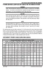
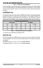
Страница 18: ...ed in the N6000 Torch Packages accepts ordinary shop compressed air Use at least 60 psi input of compressed air to the regulator Table 3 shows recommended pressure and volume inputs Compressed Air Requirements Air Pressure Air Volume psi Kg cm2 Cfm M3 min 60 4 2 46 1 3 80 5 6 63 1 8 100 7 0 81 2 3 TABLE 3 COMPRESSED AIR INPUT REQUIREMENTS To convert psi to kpa kilopascals multiply by 6 895 MAIN AI...

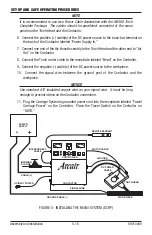
Страница 19: ...hrough each step Avoid crimping hoses or wires NOTICE When using the N6000 System with a Climber Tractor or equivalent travel system the Contactor should be centrally placed CONNECTING STEPS 1 Screw the air regulator into the Air In receptacle on the Contactor 2 Connect the shop compressed air supply to the air regulator 3 Connect one end of the Interconnect Cable to the receptacle labeled To Auto...

Страница 20: ... Head on the Controller 9 Connect the negative cable s of the DC power source to the workpiece 10 Connect the signal wire between the ground post of the Contactor and the workpiece NOTICE Use standard 12 insulated copper wire as your signal wire It must be long enough to prevent stress on the Contactor connection 11 Plug the Carriage System s grounded power cord into the receptacle labeled Travel ...

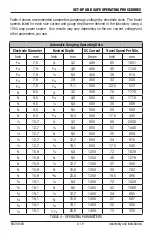
Страница 21: ...6 914 5 16 7 9 5 16 7 9 450 33 838 5 16 7 9 7 16 11 1 500 22 5 572 3 8 9 5 1 8 3 2 500 70 1778 3 8 9 5 3 16 4 8 500 44 1118 3 8 9 5 1 4 6 4 500 35 889 3 8 9 5 3 8 9 5 500 20 508 3 8 9 5 9 16 14 3 500 17 5 445 1 2 12 7 1 8 3 2 850 96 2438 1 2 12 7 1 4 6 4 850 57 1448 1 2 12 7 3 8 9 5 850 35 889 1 2 12 7 1 2 12 7 850 24 610 1 2 12 7 3 4 19 1 850 17 5 445 5 8 15 9 1 4 6 4 1250 72 1829 5 8 15 9 3 8 9 ...

Страница 22: ...UP AND SAFE OPERATING PROCEDURES 89210000 NOTE If you want a groove depth that is greater than 1 1 2 times the diameter of the electrode being used make the groove in two or more passes Assembly And Installation ...

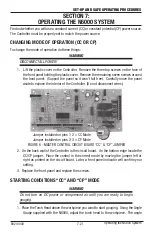
Страница 23: ...o expose the interior of the Controller Do not disconnect wires FIGURE 6 MASTER CONTROL CIRCUIT BOARD CC CP JUMPER 2 On the back wall of the Controller is the circuit board On the bottom edge locate the CC CP jumper Place the control in the correct mode by moving the jumper left or right as printed on the circuit board Later a front panel indicator will confirm your setting 3 Replace the front pan...

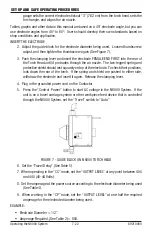
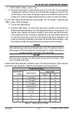
Страница 24: ...of the electrode To check their positions look down the rear of the torch If the spring and shield are pushed to either side withdraw the electrode and insert it again Release the clamping lever 4 Plug in the grounded power cord on the Contactor 5 Press the Control Power button to start AC voltage in the N6000 System If the unit is on a travel carriage system or other workpiece feed device that is...

Страница 25: ...e An arc will be struck as soon as the tip of the electrode reaches the workpiece The proper arc gap will be maintained even though the electrode feeds downward Once the electrode reaches the target depth the travel system will be energized WARNING Wear protective gear and be sure the work area is clear The system is ready to begin gouging If the unit is attached to a travel system be sure the tra...

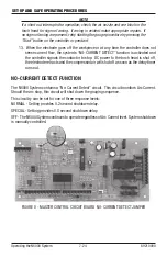
Страница 26: ...ler signals the contactor to stop DC power to the torch head is shut off the electrode retracts and the compressed air will shut off as soon as the delay timer runs out NO CURRENT DETECT FUNCTION The N6000 System contains a No Current Detect circuit This circuit monitors Arc Current Should the arc stop this circuit will shut down the gouging sequence This circuitry can be set for one of three resp...

Страница 27: ...cabinet will light if the temperature inside reaches 210 F If the unit continues to overheat the red light by the yellow will light and the system will SHUT DOWN The system can only be restarted when the internal temperatures drop to a safe level When this happens both lights will go off and then the unit will restart The cause of the overheating should be determined before restarting Refer toTrou...

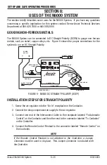
Страница 28: ...CH HEAD WORK PIECE SIGNAL WIRE GROUND CABLE CONTACTOR AC INPUT POWER CABLE INCOMING AIR LINE INTERCONNECT CABLE POWER SUPPLY FIGURE 9 N6000 DC STRAIGHT POLARITY DCEP INSTALLATION STEPS FOR STRAIGHT POLARITY 1 Screw the air regulator into the Air In receptacle on the Contactor 2 Connect the shop compressed air supply to the air regulator 3 Connect one end of the Interconnect Cable to the receptacle...

Страница 29: ...Connect the Torch motor cable to the receptacle labeled Head on the Controller 9 Plug the Carriage System s grounded power cord into the receptacle labeled Travel Carriage Power on the Controller Set the Travel Switch on the Controller to AUTO OPERATING THE N6000 SYSTEM The N6000 System works just like the operation described in the Section titled OPERATING THE SYSTEM Return to that Section to rev...

Страница 30: ...8 45 3 063 063 37 37 18 5 1 5 8 45 3 125 125 40 1 40 1 20 1 1 1 2 5 8 45 3 063 063 063 46 7 46 7 46 7 15 6 2 5 8 45 3 125 125 125 28 1 28 1 28 1 9 4 TABLE 6 J GROOVE WELD PREPARATION DATA SHEET FIGURE 10 ELECTRODE OVERHANG See Table 6 for recommended electrode overhang in a J groove weld preparation Figure 11 shows a second way to prepare a J groove weld preparation on material over 2 5 08 cm The ...

Страница 31: ...olls and shafts which needs re working Remove as much as 1 1 2 of old material from the outside diameter in a single pass and as little as 1 8 for the finish pass OSCILLATION GOUGING TO REMOVE MATERIAL UP TO 4 WIDE The N6000 can be mounted on a welding oscillator to remove material in widths up to 4 inches Normal uses for an oscillated gouge would be to remove cladded material from plates requirin...

Страница 32: ...IRDERS Backgouging the web to flange section on fabricated bridge girders is easier when using the Titan Machine Carriage and N6000 System The outrigger assembly specifically designed for this application allows the system to track off the side of the flange plate while gouging Uses of the N6000 System ...

Страница 33: ...les They protect the wheels The track is a single T bar and comes in 10 ft 3 05 m lengths One end has a protruding pin and the other end has a female slot into which the male portion of the next section fits A Pointer Assembly aligns the track so that the torch can be easily and quickly positioned over the joint POWER TheTitan Machine Carriage is for either 120VAC 60Hz or 220VAC 50Hz line voltage ...

Страница 34: ...net Support Bar Assemblies 3 per track section in the holes on the track sections Set the carriage so that the slotted guides fit over the track A manually operated clutch on the side of the carriage permits free wheeling and manual positioning of the carriage Disengage the clutch by pulling the pivoted handle Engage the clutch by pulling the handle back and moving the carriage either forward or b...

Страница 35: ...ually you can remove the Control Panel and carry it SYSTEM OPERATION To use the carriage with an automatic controller such as the N6000 System plug the power cord into the controller s receptacle Follow torch use instructions when operating the carriage with a welding or cutting torch TITAN PREVENTIVE MAINTENANCE Every six months or after each 100 hours of use coat the drive train gears with Dow C...

Страница 36: ...or on a rack attached to the track The tractor guide wheels are adjustable for wear and width variations The tractor has four wheels for better stability rigidity and ease of adjustment This rigid design is well suited for heavier or overhanging loads SAFETY CAUTION Keep hands and clothing clear from Tractor guide wheels A possible pinch point exists WARNING Protect equipment and operator from fal...

Страница 37: ...rled nuts connect sections Mounting pads supplied with the magnet clamps space the track above the work for necessary tractor clearance Track lengths 3 ft 9 m 6 ft 1 8 m 10 ft 3 05 m MAGNET CLAMP ASSEMBLIES Magnet Assemblies are shipped with keepers These should be removed before attaching the magnets to the work There is a quick release lever on each magnet When this lever is pushed to the horizo...

Страница 38: ...actor to the position you want it and lower the drive gear lever to engage the motor and gear to the rack Fine adjustment for track width may be necessary FINE ADJUSTMENT FOR TRACK WIDTH Make fine adjustments by loosening the lock nuts on the two adjustable wheel legs Rotate the flat head screw for a snug fit on the track Hold the flat head screw to prevent turning Tighten the lock nuts HORIZONTAL...

Страница 39: ...r looseness periodically and tighten CLIMBER WHEEL ADJUSTMENT Due to track wear the wheels on the Climber Tractor will require adjustment periodically The adjustable wheels are the two with the ones with the large straight bladed screwdriver slot in them Loosen the locking nut on these wheels located on the underside of the tractor base plate With a large straight bladed screwdriver rotate each wh...

Страница 40: ...ontrol panel Travel switch in MANUAL Position Defective Travel Auto Manual switch Replace switch Defective Control Power switch on control panel Replace switch No panel light illumination Absence of 24 volts in MCCB Replace MCCB Bulbs burned out May be due to excess of 24 volts in MCCB Replace bulbs if excess of 24 volts in MCCB replace MCCB Defective Control Power switch Replace switch Contactor ...

Страница 41: ...onnector s J4 J5 J6 improperly or not firmly attached on MCCB Check connector s for solid proper fit Defective MCCB Replace MCCB Defective electrode drive motor Repair replace motor Air solenoid energizes but contactor doesn t Open contactor coil Replace contactor coil assembly Defective rectifier bridge in contactor unit Replace rectifier bridge Start sequence trips circuit breaker Short in inter...

Страница 42: ...h temperature shutdown Allow contactor unit to cool check fan and filter Defective MCCB Replace MCCB Erratic or uncontrollable arc Constant current CC constant potential CP toggle switch on MCCB improperly set Reread Section entitled Starting Conditions Using improper torch operating conditions for electrode size diameter See Chart 1 for proper operating conditions Insufficient arc voltage due to ...

Страница 43: ...l only Check replace Contactor unit in high temperature shut down Allow contactor unit to cool check fan and filter Fan does not run with control panel ON Break in interconnect cable which links contactor to controller Check replace Defective fan Check replace Defective transformer in contactor 220 VAC model only Check replace Travel does not begin after arc is struck Travel switch on control pane...

Страница 44: ...oning damaged Repair replace cables Connector s J4 J5 J6 improperly or not firmly connected on MCCB Check connector s for solid proper fit Break in interconnect cable which links control panel to contactor Repair replace interconnect cable Defective DC Volt meter Check replace meter Wrong polarity Straight polarity the DC Volt meter reading will be reversed Connect power cables to power source and...

Страница 45: ...x convenient outlet Absence of appropriate power Check power continuity from source to tractor Tripped breaker on the tractor Reset breaker Loose connection on the outlet Check connections on the inside enclosure and secure Defective outlet Replace outlet Tractor will not run with the switch in the auto mode Absence of voltage to receptacle Check repair as required Tripped breaker on the tractor R...

Страница 46: ...y Replace transformer Tractor loose on the track Track section is worn Reset adjustable wheel legs See Section Climber Wheel Adjustment Replace track section Adjustable wheel legs are loose Reset adjustable wheel legs and re lock TITAN MACHINE CARRIAGE Problem Possible Cause Possible Remedy Carriage will not run with switch in the ON position Engagement lever is not engaged Place lever in engage p...

Страница 47: ...he outlet Check connections on the inside enclosure and secure Defective outlet Replace outlet No control of travel speed Loose set screw on potentiometer Tighten set screw Defective potentiometer Replace potentiometer Defective motor speed control Replace motor speed control Fuse for the carriage keeps blowing Defective motor speed control Replace motor speed control Defective motor Replace motor...

Страница 48: ...nnect Cable Connector 96 169 329 Stop Switch 96 834 331 Capacitor 96 131 010 Start Switch 96 834 332 Resistor 96 696 029 Travel Switch 96 834 334 Electrode Jog Switch 96 834 333 Volt Meter 96 508 036 Control Power Switch 96 834 330 Ampere Meter 96 508 037 Transformer 96 881 084 Plastic Cover Assembly 94 171 270 Front Panel Screws 1 32 x 3 8 97 152 072 Jumper Connector Assembly 96 169 352 N6000 CON...

Страница 49: ...enum 94 636 001 26 Insulator 94 433 184 8 Air Nozzle w Insulator 94 556 071 28 Drive Motor 96 524 095 9 Interconnect Bar 96 070 030 29 Electrode Holder Tube 94 893 082 10 Interconnect Jumper 96 458 021 33 Cable Boot 94 105 016 Shoe Buss Bar 96 774 096 35 Adapter 94 013 097 11 Buss Bar 94 070 029 36 Brass Street Elbow 94 306 151 12 Tinned Flat Copper Braid 96 458 025 37 Guide Block 94 096 133 13 Ju...

Страница 50: ...le 96 130 254 15 4 0 Power Cable 96 130 256 Air Hose Assembly Part No 25 4 0 Power Cable 96 130 300 4 Air Hose 94 396 051 50 4 0 Power Cable 96 130 301 15 Air Hose 94 396 049 25 Air Hose 94 396 048 Motor Cable Assembly Part No NOTE when distance is greater than 25 ft air hose inside diameter should be or greater 3 Head Motor Cable 96 130 257 12 Head Motor Cable 96 130 253 15 Head Motor Cable 96 13...

Страница 51: ...EDURES 12 49 89210000 TITAN MACHINE CARRIAGE REPLACEMENT PARTS Description Part no 120 Volt 60 Hz Titan Carriage 71 022 501 Front Wheel Assembly 95 949 022 Speed Control Board 96 174 061 Cleaning Brushes 94 122 055 Relacement Parts ...

Страница 52: ... de Janeiro Brazil Customer Care Ph 55 21 2485 8998 Fax 55 21 2485 8866 Chorley United Kingdom Customer Care Ph 44 1257 261755 Fax 44 1257 224800 Milan Italy Sales Office Ph 39 02 98 80320 Fax 39 02 98 281773 Cikarang Indonesia Customer Care Ph 62 21 8983 0011 0012 Fax 62 21 893 6067 Osaka Japan Sales Office Ph 816 4809 8411 Fax 816 4809 8412 Melbourne Australia Customer Care Ph 1300 654 674 Fax 6...

Отзывы: