Arbor Technology FPC-8100 Series Скачать руководство пользователя страница 58

- 46 -

Installation & Maintenance

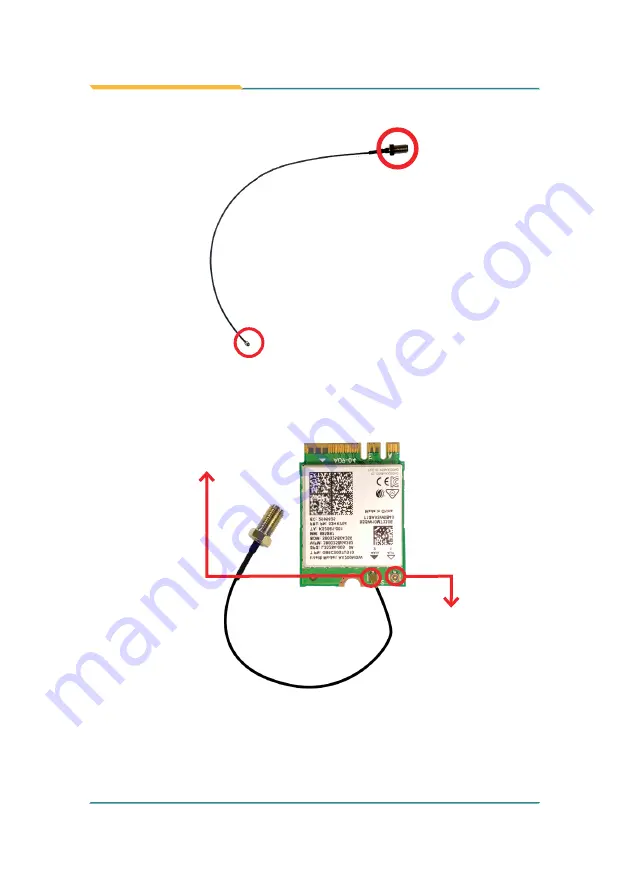
and an MHF connector on the other.

SMA connector

MHF connector

5.  Connect the RF antenna’s MHF connector to the Wi-Fi module’s main 

connector marked 0. If you are going to connect a secondary antenna, 

connect it to the connector marked 1. 

6.  Plug the Wi-Fi module to the socket’s connector by a slanted angle. Fully 

plug the module, and note the notch on the wireless module should meet 

the break of the connector.


Connect the RF antenna’s 

MHF connector to the Wi-Fi 

module’s main connector 

(marked 2)

Connect the secondary RF 

antenna’s MHF connector to 

the Wi-Fi module’s secondary 

connector (marked 1)

Содержание FPC-8100 Series

Страница 1: ...1 FPC 8100 Series Robust Box PC with Intel 10th Generation CoreTM i9 i7 i5 i3 Processor User s Manual Version 1 0 2021 02 P N 4016810000100P...

Страница 2: ...2 This page is intentionally left blank...

Страница 3: ...i Revision History Version Release Time Description 1 0 2021 02 Initial release...

Страница 4: ...ories 6 1 5 2 Configure to Order Service 6 Chapter 2 System Overview 8 2 1 Dimensions 9 2 2 Take A Tour 10 2 2 1 FPC 8100 10 2 2 2 FPC 810X 11 2 3 Driver Installation Notes 12 Chapter 3 System Configu...

Страница 5: ...anced 61 5 2 1 CPU Configuration 62 5 2 2 Trusted Computing 64 5 2 3 ACPI Settings 65 5 2 4 Super IO Configuration 66 5 2 5 Hardware Monitor 69 5 2 6 S5 RTC Wake Settings 70 5 2 7 PCI Sybsystem Settin...

Страница 6: ...iv This page is intentionally left blank...

Страница 7: ...rer Declaration of Conformity CE The CE symbol on the computer indicates that it is in compliance with the directives of the Union European EU A Certificate of Compliance is available by contacting Te...

Страница 8: ...ve was published on 2 13 2003 The main purpose of the directive is to prohibit the use of lead mercury cadmium hexavalent chromium polybrominated biphenyls PBB and polybrominated diphenyl ethers PBDE...

Страница 9: ...OVER THE OPENINGS 7 Position the power cord so that people cannot step on it Do not place anything over the power cord 8 Never pour any liquid into opening This may cause fire or electrical shock 9 Ne...

Страница 10: ...with the Box PC whenever components are separated from the system Replacing Lithium Battery Incorrect replacement of the lithium battery may lead to a risk of explosion The lithium battery must be rep...

Страница 11: ...misuse of or inability to use this product Vendor will not be liable for any claim made by any other related party Vendors disclaim all other warranties either expressed or implied including but not...

Страница 12: ...x This page is intentionally left blank...

Страница 13: ...1 1 Chapter 1 Introduction Chapter 1 Introduction...

Страница 14: ...ed 1 x 2 5 Gigabit LAN support 1 x M 2 E Key 2230 for WiFi BT Front accessible I O support 1 2 About this Manual This manual is meant for the experienced users and integrators with hardware knowledge...

Страница 15: ...WGI219LM GbE controller w o iAMT H420E w iAMT W480E Watchdog Timer 1 255 levels reset I O Serial Port 2 x RS 232 422 485 configurable via DB 9 connectors 4 x RS 232 ports via DB 9 connectors USB Port...

Страница 16: ...g Vibration 3 Grms 5 500Hz random operation w SSD Shock Operating 40G 11ms Non operating 60G with SSD Qualification Certification CE FCC Class A Power Requirement Power Input DC 9 36V input w 4 pin DC...

Страница 17: ...5 Introduction OS Support Windows 10 IOT Enterprise 64 bit Linux Kernel 4 9...

Страница 18: ...1 Optional Accessories The following items are normally optional but some vendors may include them as a standard package or some vendors may not carry all the items WMK 7000 Wall mount kit for FPC 7X...

Страница 19: ...L2 20M 1 8G Core i7 10700E Intel 10th Gen Core i7 10700E processor L2 16M 2 9G Core i7 10700TE Intel 10th Gen Core i7 10700TE processor L2 16M 2 0G Core i5 10500E Intel 10th Gen Core i5 10500E process...

Страница 20: ...8 2 Chapter 2 System Overview Chapter 2 System Overview...

Страница 21: ...9 System Overview 2 1 Dimensions FPC 8100 90 00 96 00 225 00 250 00 238 00 UBC 6 32 4 00 6 00 292 00 112 00 92 00 112 00 92 00 FPC 810X...

Страница 22: ...rts USB 2 0 Ports GbE LAN Port Antenna holes DVI D Ports VGA Ports DIO LPT Port Optional Power Button CFast Card Window 2 2 1 2 Rear View Ignition Switch DC IN USB 3 2 Ports GbE LAN Ports HDMI Port Gr...

Страница 23: ...Ports GbE LAN Port USB 3 2 Ports DVI D Ports CFast Card Window DIO LPT Port Optional Power Button 2 2 2 2 Rear View RS 232 Serial Ports Ignition Switch DC IN HDMI Port PCI PCIe slots GbE LAN Ports USB...

Страница 24: ...he product page Then extract the down loaded file and follow the sequence below to install the drivers Chipset Graphic Audio Other drivers The driver path is listed as below Windows 10 Driver Path Chi...

Страница 25: ...13 3 Chapter 3 System Configuration Chapter 3 System Configuration...

Страница 26: ...1 4 4 1 4 2 3 1 L1 L2 L2 L1 1 3 2 4 C2 1 2 9 10 22 23 24 25 1 2 3 4 5 1 2 10 9 B1 B6 A1 A6 A5 A9 B5 B9 B1 B6 A1 A6 A5 A9 B5 B9 B1 B6 A1 A6 A5 A9 B5 B9 X1 X3 X4 X2 18 14 4 1 X1 X3 X4 X2 18 14 4 1 PC1...

Страница 27: ...m 1 4 4 4 2 3 1 1 1 1 1 1 2 3 4 5 6 7 1 2 3 4 5 6 7 1 9 1 9 9 1 9 1 1 1 B 1 A 1 B 4 9 A 4 9 B 1 A 1 B 8 2 A 8 2 VGACARDPWR01 USB4 COM7 USB5 21 PWROUT1 22 SATA1 23 SATA2 24 PWROUT2 25 COM4 26 COM5 27 C...

Страница 28: ...PWRIN1 DC adapter power input POEOUT1 PoE power connector SW2 System switch JACCON2 Ignition Power connector DIO1 Digital IO Connector LPT1 On board parallel port connector CPUFAN1 Fan power connecto...

Страница 29: ...or 31 PCIE1 PCI Expansion Slot 32 PCIE2 PCI Expansion Slot 33 VGA1 Analog RGB DVI D connector 34 35 36 USB1 2 3 USB 2 0 3 0 connectors 37 LAN1 RJ 45 Ethernet connector 38 PWRIN3 DC Adapter Power Input...

Страница 30: ...on Short Clear CMOS 1 2 Open Keep CMOS default 1 2 JACCON1 Function ACC ON Mode selection for debug Jumper Type 2 00mm pitch 1x2 pin header Setting Pin Description Short ACC ON Mode 1 2 Open Car mode...

Страница 31: ...ption 1 4 1 GND 2 12V 3 RPM 4 Control System reset pin header JSW1 Function Reserved for Reset button Connector Type onboard 2 0mm pitch 2 pin header Pin Assignment Pin Description 1 2 1 FR_RST 2 GND...

Страница 32: ...5 nPMALERT 6 PMSDA PWRIN1 Function DC IN Power Connector Connector Type 2 54mm pitch 4 pin header Pin Assignment Pin Description 4 3 1 1 GND 2 GND 3 DCIN 4 DCIN POEOUT1 Function PoE Power Connector C...

Страница 33: ...tion 1 1 Acc_ON 2 GND DIO1 Function Digital IO Connector Connector Type 2 0mm pitch 2x13 pin box header Pin Assignment Pin Desc Pin Desc 14 1 26 13 1 DIO0 14 DIO8 2 DIO1 15 DIO9 3 DIO2 16 DIO10 4 DIO3...

Страница 34: ...or Connector Type 2 00mm pitch 2 x13 pin box header Pin Assignment Pin Desc Pin Desc 14 1 26 13 1 STB 14 AFD 2 PD0 15 ERR 3 PD1 16 INIT 4 PD2 17 SLIN 5 PD3 18 GND 6 PD4 19 GND 7 PD5 20 GND 8 PD6 21 GN...

Страница 35: ...Pin Assignment Pin Desc Pin Desc PC1 PC17 S7 S1 S1 SGND1 PC6 TBD S2 TXP PC7 GND S3 TXN PC8 LED1 S4 SGND2 PC9 LED2 S5 RXN PC10 IO1 S6 RXP PC11 IO2 S7 SGND PC12 IO3 PC1 CDI PC13 3 3V PC2 GND PC14 3 3V P...

Страница 36: ...ment Pin Desc Pin Desc 1 2 15 16 1 RED 9 5V 2 GREEN 10 GND 3 BLUE 11 N C 4 N C 12 VDDAT 5 GND 13 HSYNC 6 GND 14 VSYNC 7 GND 15 VDCLK 8 GND MEKEY1 Function M 2 E Key socket w PCIe USB 2 0 for optional...

Страница 37: ...onnector Pin Assignment 52 51 16 18 15 17 2 1 SMBUS Connector JSMB1 Function SMbus Wafer connector for DIO Connector Type 1 25mm pitch 1x6 wafer connector Pin Assignment Pin Desc 1 V3 3S 2 GND 3 CLK 4...

Страница 38: ...2 GND 3 V12S 4 V12S 21 USB4 5 Function USB 3 0 2 0 Connectors Connector Type On board 1 25mm pitch 1x5 pin wafer connector Pin Assignment Pin Description 1 1 5V 2 D 3 D 4 GND 5 GND 22 25 PWROUT1 2 Fu...

Страница 39: ...bdard 7 pin Serial ATA Connector Pin Assignment Pin Description 1 7 1 GND 2 TX 3 TX 4 GND 5 RX 6 RX 7 GND 26 27 COM4 5 Function RS232 Connector COM4 COM5 Connector Type Onboard 1 25mm pitch 9 pin Conn...

Страница 40: ...5 XTXD 6 XCTS 7 XDTR 8 XRI 9 GND 30 SYSFAN2 Function System Fan power out Connector Type 2 0mm pitch 2 pin header Pin Assignment Pin Description 1 1 12V 2 GND 31 PCIE1 Function PCIe x4 slot Pin Assign...

Страница 41: ...13 HSYNC 4 N C 9 5V 14 VSYNC 5 GND 10 GND 15 VDCLK DVI D Connector Pin Desc Pin Desc Pin Desc 1 TMDS Data 2 9 TMDS Data 1 17 TMDS Data 0 2 TMDS Data 2 10 TMDS Data 1 18 TMDS Data 0 3 GND 11 GND 19 GND...

Страница 42: ...al block Pin Assignment Pin Desc 1 2 3 4 1 VIN 2 VIN 3 Switch 4 Switch 39 LAN2 Function Dual GbE RJ 45 Ethernet connectors 8 1 8 1 Connector Type RJ 45 connector that supports 10 100 1000Mbps fast Eth...

Страница 43: ...rnal double stacked 9 pin D sub male connector Pin Assignment RS 232 Pin Desc Pin Desc 5 1 6 9 5 1 6 9 1 DCD RS422 TX RS485 6 DSR 2 RXD RS422 TX RS485 7 RTS 3 TXD RS422 RX 8 CTS 4 DTR RS422 RX 9 RI 5...

Страница 44: ...tacked 9 pin D sub male connector Pin Assignment Pin Description Pin Description 5 1 6 9 5 1 6 9 1 DCD 6 DSR 2 RXD 7 RTS 3 TXD 8 CTS 4 DTR 9 RI 5 GND COM3 4 COM5 6 COM3 4 COM5 6 43 Audio1 Function Aud...

Страница 45: ...33 4 Chapter 4 Installation and Maintenance Chapter 4 Installation and Maintenance...

Страница 46: ...computer and access the inside Follow through the steps below to remove the top cover and bottom cover from the computer 4 1 1 2 Remove Top Cover All jumpers CPU socket MiniCard socket SDRAM SO DIMM s...

Страница 47: ...ce 3 Carefully lift the top cover and then completely part the top cover from the computer The inside of the computer comes to view FPC 810X 1 Place the computer on a flat surface Loosen and remove th...

Страница 48: ...ance 2 Loosen and remove the 2 screws on the front and rear panels respectively as shown below 3 Carefully lift the top cover and then completely part the top cover from the computer The inside of the...

Страница 49: ...omputer s bottom cover has to be removed Follow through the steps below to remove the bottom cover from the computer FPC 8100 1 Remove the top cover as desribed in 4 1 1 2 Remove Top Cover on page 34...

Страница 50: ...carefully lift and remove the bottom cover from the computer The bottom of the computer comes to view 4 1 2 Install CPU 1 Remove the top cover from the computer as described in 4 1 1 2 Remove Top Cov...

Страница 51: ...cessor socket comes with a lever to secure the processor Please refer to the pictures step by step as below and note that the cover of the socket must always be installed during transportation to avoi...

Страница 52: ...ipset Heat sink for models w SMART FAN Fan connectors 4 Apply the thermal paste to the CPU 5 Place the heat sink on the CPU and PCH Make sure that the thermal pad is in complete contact with the PCH c...

Страница 53: ...tall Memory Modules The main board has two memory module DIMM sockets Increase memory capacity to make programs run faster on the system The memory module for the FPC 8100 Series SO DIMM sockets shoul...

Страница 54: ...he top cover from the computer as described in 4 1 1 2 Remove Top Cover on page 34 2 Locate the SO DIMM sockets on the main board The SO DIMM sockets are vertical type and each socket has two latches...

Страница 55: ...de at the SO DIMM socket Position the memory module at the SO DIMM socket with the memory module s key notch aligned at the break of the SO DIMM s slot connector 5 Vertically plug the memory module to...

Страница 56: ...ntenance To uninstall a DDR4 memory module 1 Pull back both latches from the SO DIMM socket The DDR4 memory module will be auto released from the socket 2 Remove the memory module 3 Restore the top co...

Страница 57: ...over on page 34 2 Locate the M 2 E Key socket for wireless module 3 Prepare the Wi Fi module kit The module is a M 2 E Key socket form factor with two U FL connectors one is MAIN and the other is AUX...

Страница 58: ...condary antenna connect it to the connector marked 1 6 Plug the Wi Fi module to the socket s connector by a slanted angle Fully plug the module and note the notch on the wireless module should meet th...

Страница 59: ...hole Keep the plastic plug for any possible restoration in the future FPC 8100 FPC 810X 9 From the other end of the RF antenna which is an SMA connector remove the washer and the nut Note the SMA con...

Страница 60: ...tenna hole 11 Mount the washer first and then the nut to the SMA connector Make sure the nut is tightened Mount the washer and the nut to the SMA connector Tighten the nut 12 Have the external antenna...

Страница 61: ...w Then dismount the brackets from the computer 3 Attached the SATA cable to the HDD SSD storage device Slide the HDD SSD storage device into the bracket and fix the storage device in place by fastenin...

Страница 62: ...ess Cards for FPC 810X Only To install a PCI or PCI Express card 1 Remove the bottom cover from the computer as described in Section 4 1 1 3 Remove the Bottom Cover on page 37 2 Use a cross head screw...

Страница 63: ...lot Follow through the guide below to install a CFast card to the computer This section will use FPC 810X as the installation example Note Be sure to turn off the computer before installing or uninsta...

Страница 64: ...and open the card door 2 Push eject the CFast card 3 Remove the CFast card 4 Refasten the screw to close the card door Note Make sure to refasten the screw to close the card door each time the CFast c...

Страница 65: ...SIM card holder cover towards the OPEN edge and then lift the cover to open it 4 Insert the SIM card into the card holder as shown below 5 Close the SIM card holder door and slide the door to the LOCK...

Страница 66: ...door each time the SIM card is installed or uninstalled 4 2 Ground the Computer Follow the instructions below to ground the computer to land Be sure to follow every grounding requirement in your place...

Страница 67: ...res of the DC power source 4 Identify the positive and negative feed positions for the terminal block connection See the symbols printed on the rear panel indicating the polarities and DC input power...

Страница 68: ...vehicle power source 1 Make sure JACCON2 jumper is open for vehicle power mode Refer to Section 3 2 1 Jumpers on page 18 2 For vehicle application DC power Input wiring pin configuration is as below P...

Страница 69: ...57 5 Chapter 5 BIOS Chapter 5 BIOS...

Страница 70: ...the computer is off the battery on the main board supplies power to BIOS RAM To enter the BIOS Setup utility keep hitting the Delete key upon powering on the computer The featured settings are Menu De...

Страница 71: ...to the top menu Page Up Increases current value to the next higher value or switches between available options Page Down Decreases current value to the next lower value or switches between available...

Страница 72: ...tion System Date Set the system date Use Tab to switch between Data elements Note that the Day automatically changes when you set the date The date format is Day Sun to Sat Month 1 to 12 Date 1 to 31...

Страница 73: ...page 65 Super IO Configuration See 5 2 4 Super IO Configuration on page 66 Hardware Monitor See 5 2 5 Hardware Monitor on page 69 SS RTC Wake Settings See 5 2 6 S5 RTC Wake Settings on page 70 PCI Su...

Страница 74: ...r Threading Technology When disabled only one thread per enabled core is enabled Intel VMX Virtualization Technology Whenenabled aVMMcanutilizetheadditionalhardware capabilities provided by Vanderpool...

Страница 75: ...63 BIOS C States Enable Disable default CPU power management Allows CPU to go to C state when it s not 100 utilized...

Страница 76: ...ption Security Device Support Enable default or Disable BIOS support for security device Pending operation Schedule an Operation for the security Device Your computer will reboot during restart in ord...

Страница 77: ...efault BIOS ACPI Auto Configuration Enable Hibernation Enables default or Disables System ability to Hibernate OS S4 Sleep State This option may be not effective with some OS ACPI Sleep State Select A...

Страница 78: ...tion Serial Port Configuration Serial Port Enable default or Disable Serial Port COM Mode Select Select RS 232 default RS 422 RS 485 RS 422 Termination Resistor or RS 485 Termination Resistor Parallel...

Страница 79: ...67 BIOS Device Mode Change the printer port mode Options STD Printer Mode default SPP Mode EPP 1 9 and SPP Mode EPP 1 7 and SPP Mode ECP Mode ECP and EPP 1 9 Mode ECP and EPP 1 7 Mode...

Страница 80: ...68 BIOS Super IO Chip F81216SEC Settings Serial Port Configuration Serial Port Enable default or Disable Serial Port COM...

Страница 81: ...bles default or Disables Smart Fan SYSFAN SmartFan Function Boundary 1 4 Segment Speed 1 5 Auto fan speed control Fan speed will follow different temperature by different PRM 1 100 Note CPUFAN SYSFAN...

Страница 82: ...stem from S5 Enable or Disable default system wake on alarm event Options available are Disabled default Fixed Time System will wake on the hr min sec specifiedc DynamicTime If selected you need to se...

Страница 83: ...ter Options 32 default 64 96 128 160 192 224 and 248 PCI Bus Clocks PCI X Latency Timer Value to be programmed into PCI X Latency Timer Register Options 32 64 default 96 128 160 192 224 and 248 PCI Bu...

Страница 84: ...no USB device are connected Select Disabled to keep USB devices available only for EFI applications XHCI Hand off This is a workaround for OSes without XHCI hand off support The XHCI ownership change...

Страница 85: ...set maximum time the device will take before it properly reports itself to the host controller Auto uses default value for a root port it is 100 ms for a hub port the delay is taken from hub descripto...

Страница 86: ...y Network Control the execution of UEFI and Legacy PXE OpROM Options Do not launch default UEFI and Legacy Storage Control the execution of UEFI and Legacy Storage OpROM Options Do not launch and Lega...

Страница 87: ...75 BIOS 5 2 10 NVMe Configuration Access this submenu to view the NVMe controller and driver information...

Страница 88: ...is submenu to view the memory configuration Graphics Configuration See 5 3 1 1 Graphics Configuration on page 78 PEG Port Configuration PEG port options Enable Root Port Enable or Disable the root por...

Страница 89: ...size is set to 2048MB PCH IO Configuration SATA And RST Configuration See 5 3 1 2 SATA And RST Configuration on page 80 USB Configuration See 5 3 1 3 USB Configuration on page 81 State After G3 Specif...

Страница 90: ...GFX PEG and PCI Internal Graphics Enables disables the IGD Options available are Auto default Disabled and Enabled GTT Size Select the GTT Size Options 4MB 2MB and 8MB default Apeture Size Select the...

Страница 91: ...DVMT 5 0 Pre allocated Fixed Graphic Memory size used by the Internal Graphic Device 32M is the default DVMT Total Gfx Mem Select the DVMT 5 0 Total Graphic Memory size used by the Internal Graphic De...

Страница 92: ...cription SATA Controller s Enables default Disables SATA device s Aggressive LPM Support Enables Disables default PCH to aggressively enter link power state Serial ATA Port 0 3 SATA device information...

Страница 93: ...s settings are Setting Description XHCI Disable Compliance Mode Options to disable Compliance Mode Default is FALSE default to not disable Compliance Mode Set TRUE to disable Compliance Mode xDCI Supp...

Страница 94: ...To set up an administrator password 1 Select Administrator Password 2 An Create New Password dialog then pops up onscreen 3 Enter your desired password that is no less than 3 characters and no more th...

Страница 95: ...e boot Secure Boot Mode Allow users to set the secure boot selector Standard Custome default mode Restore Factory Keys Force system to restore default secure boot key database Reset to Setup Mode Dele...

Страница 96: ...tely Bootup NumLock State Sets whether to enable or disable the keyboard s NumLock state when the system starts up Options available are On default and Off Quiet Boot Sets whether to display the POST...

Страница 97: ...rt power delay function Options Enable default Support power delay function Disable Power on off manually operated Power on delay Select the time which the system will power on Options Manually Operat...

Страница 98: ...Defaults Restores all settings to defaults This is a command to launch an action from the BIOS Setup utility Boot Override Boot Override presents a list in context with the boot devices in the system...

Страница 99: ...87 Appendices Appendices Appendices...

Страница 100: ...tten in C for the digital I O application example Sample Codes include math h include stdio h include dos h int sioIndex 0x2E int sioData 0x2F int main void int iData SioGPIOMode 0xFF00 delay 2000 Sio...

Страница 101: ...oData iTemp outportb sioIndex 0xAA Disable Super I O void SioGPIOData int iData int iTemp outportb sioIndex 0x87 Enable Super I O outportb sioIndex 0x87 outportb sioIndex 0x07 Select logic device GPIO...

Страница 102: ...outportb sioIndex 0x07 Select logic device GPIO outportb sioData 0x06 outportb sioIndex 0xA2 GPIO 50 57 Status iTemp inportb sioData outportb sioIndex 0xF2 GPIO 00 07 Status iStatus inportb sioData ou...

Страница 103: ...system then WDT will time out and auto reset the system to avoid abnormal operation This computer supports 255 levels watchdog timer by software programming I O ports Below is an assembly program exam...

Страница 104: ...x 0xF5 Set Configure and Enable WDT timer Start countdown outportb sioData 0x32 outportb sioIndex 0xAA Disable Super I O void SioWDTStop void outportb sioIndex 0x87 Enable Super I O outportb sioIndex...

Страница 105: ...t outportb sioIndex 0xAA Disable Super I O int SioWDTCount void int iData outportb sioIndex 0x87 Enable Super I O outportb sioIndex 0x87 outportb sioIndex 0x07 Select logic device WDT outportb sioData...

Отзывы: