- 35 -
System Configuration
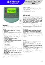
MC3
Description:
PCI Express Mini-card socket
Connector Type:
Onboard 0.8mm-pitch 52-pin
edge card connector
Pin Desc.
Pin Desc.
1
WAKE#
16 N/C
2 +3.3V
17 N/C
3 N/C
18 GND
4 GND
19 N/C
Pin Desc.
Pin Desc.
5 N/C
20
W_DISABLE#
31
PE_CAD3_TX-
42
3G_LED_A
6 +1.5V
21 GND
32
SMB_DATA
43 GND
7
CLKREQ#
22
PCIE_ARST#
33
PE_
44 N/C
8
UIM_PWR_A
23
PE_CAD3_RX-
34 GND
45 N/C
9 GND
24 +3.3V
35 GND
46 N/C
10
UIM_DATA_A
25
PE_
36
USB_D-
47 N/C
11 REFCLK-
26 GND
37 GND
48 +1.5V
12
SIM_CLK_A
27 GND
38
USB_D+
49 N/C
13
28 +1.5V
39 +3.3V
50 N/C
14
UIM_RST_A
29 GND
40 GND
51 N/C
15 GND
30
SMB_CLK
41 +3.3V
52 +3.3V
52
51
16
18
15
17
2
1
Board Top
1
5 1
5
B1
B6
A1
A6
A5
A9
B5
B9
17
9
1
24
16
8
C15
C10
C5
C11
C6
C1
3
4
2
1
1
C6
C5
C4
C3
C2
C1
SW1
SW2
L2
L1
2
4
6
4
3
1
ON
2
3
1
4
3
2
1
1
2
9
10
+
1
1
3
2
1
1
D
D
1
C1
A1
C2
A2
C1
A1
C2
A2
C1
A1
C2
A2
C1
A1
C2
A2
1
2
5
6
1
2
3
4
5
6
7
6
1
10
5
X1
X3
X4
X2
18
14
4
1
35
36
33
34
11
14
19
15
21
29
24
25
B14
B11
A14
A11
B10
B2
B1
B9
A9
A10
A2
A1
1
2
17
15
18
16
51
52
1
2
17
15
18
16
51
52
1
2
17
15
18
16
51
52
1
2
17
15
18
16
51
52
ROUTE
ROUTE
Содержание ARTS-4770
Страница 2: ...2 Revision History Version Release Time Description 1 0 May 2014 Initial release...
Страница 10: ...viii This page is intentionally left blank...
Страница 11: ...1 1 Chapter 1 Introduction Chapter 1 Introduction...
Страница 16: ...6 This page is intentionally left blank...
Страница 17: ...7 2 Chapter 2 Getting Started Chapter 2 Getting Started...
Страница 22: ...12 This page is intentionally left blank...
Страница 23: ...13 3 Chapter 3 System Configuration Chapter 3 System Configuration...
Страница 27: ...17 System Configuration PBC 1916 Board Bottom...
Страница 36: ...26 System Configuration Board Bottom...
Страница 52: ...42 This page is intentionally left blank...
Страница 53: ...43 4 Chapter 4 Installation and Maintenance Chapter 4 Installation and Maintenance...
Страница 65: ...55 5 Chapter 5 BIOS Chapter 5 BIOS...
Страница 88: ...78 This page is intentionally left blank...
Страница 89: ...79 Appendices Appendices...
Страница 94: ...84 Appendices 13 Have an external antenna Screw and tightly fasten the antenna to the SMAconnector...
Страница 103: ...93 This page is intentionally left blank...