54
Timing, IRIG-B and Pulses
8.4
Connecting the Outputs
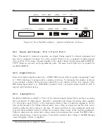
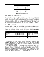
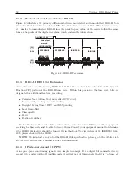
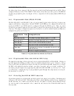
All clocks come equipped with Phoenix-style, screw terminal connectors, which are compatible
with twisted pair cabling. To attach, strip the wires bare, DO NOT tin with solder, insert into the
correct screw terminal positions and tighten clockwise. To adapt coaxial cabling to the 1092/93
terminal connectors, use a BNC Breakout
, or other similar adapter.
NOTE: If using a shielded, twisted-pair cable (like Belden 8760), connect the cable shield at
the clock. It has become best industry practice to ground time-code outputs from clocks, and use
galvanic isolation of time code inputs to IEDs.
8.4.1
Attaching Cables to Screw Terminals
Prepare the twisted pair cable by stripping back at least 1/4” of the insulation and any shielding;
DO NOT tin the bare wire with solder. Tighten the screws (clockwise) down on the wire.
8.4.2
How Far Can I Run IRIG-B Cabling?
Before laying cable to transmit IRIG-B over long distances, take time to consider the following
factors: (1) resistive losses in cabling, (2) electromagnetic interference, (3) propagation delays, and
(4) installation and maintenance costs.
Realize that when cable is laid from point A to point B that two cables are involved: one
outgoing and one return. For coaxial cable, the resistance is different for the center conductor than
for the outer conductor, or shield. For twisted pair wires, both outgoing and return wires will be
the same. As a simple example, to connect an IRIG-B signal to a device 100 feet away from the
clock, you must account for resistive losses in 200 feet of wire.
For details on distributing IRIG-B signals over long distances, see application note, AN101,
Distributing Timing Signals in a High-EMI Environment. Download file appnote101.pdf at the
following link:
http://www.arbiter.com/resources/documentation.php
For important considerations about IRIG-B connections, distribution of signals and accuracy,
download the following file from the same link.
IRIG-B accuracy and connection requirements.pdf at the same link above.
8.4.3
Synchronizing Multiple IED’s From One Masterclock Output
In many installations, master clock signals are “fanned out” to a number of devices. This method
makes more efficient use of the clock synchronizing capability since the clock drivers are designed
to handle multiple loads. The exact number of possible loads must be determined from the input
impedance of each connected IED.
2
Pomona Electrics, www.pomonaelectronics.com, (800) 444-6785, (425) 446-6010, part no. 4969 and 4970
3
William Dickerson, “Time in the Power Industry: How and Why We Use It,” www.arbiter.com, Resources,
Documentation
Содержание 1092A
Страница 4: ...iv ...
Страница 18: ...xviii LIST OF TABLES ...
Страница 129: ...C 10 Option 20A Four Fiber Optic Outputs 111 Figure C 7 Option 20A Jumper Locations ...
Страница 131: ...C 11 Option 27 8 Channel High Drive 113 Figure C 8 Option 27 Jumper Locations ...
Страница 148: ...130 Options List Figure C 10 Option 29 Connector Signal Locations ...

