background image

10

FastSCAN

Note

- Multiple standard

FastSCAN

TM

systems will not work alongside one another

without interference. This can be remedied with a replacement Frequency Module.
Contact your vendor if required.

3.2

The Wand

The

FastSCAN

TM

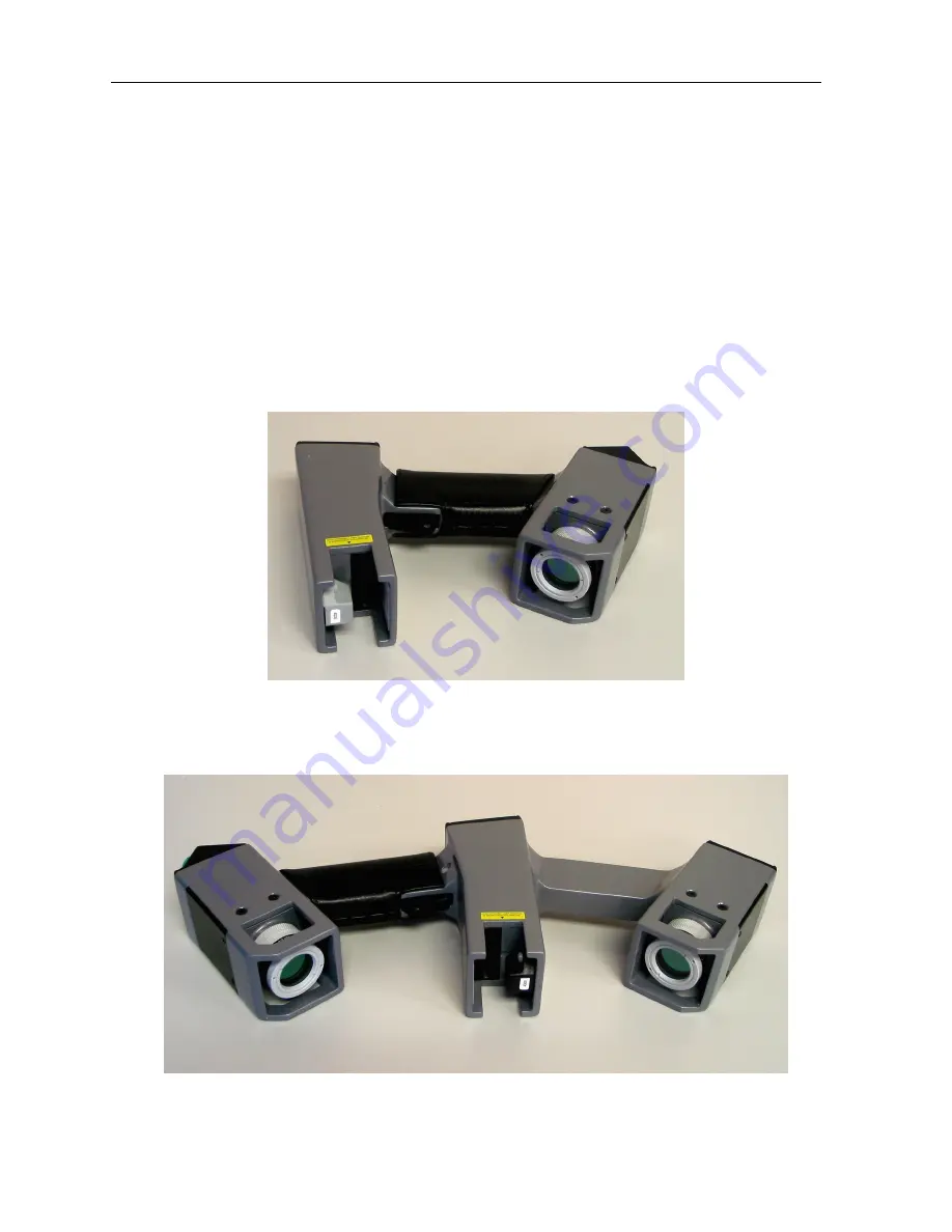
Wand is available in 2 models—the

Cobra

TM

and the

Scorpion

TM

.

The

Cobra

TM

is a light and compact single-camera Wand suited to most applica-

tions. The double-camera

Scorpion

TM

can enable faster scanning and be more ef-

fective where occlusion is potentially a problem.

Figure 7: The

Cobra

TM

Wand.

Figure 8: The

Scorpion

TM

Wand.

Содержание FastSCAN Cobra

Страница 1: ...FastSCAN TM Cobra TM and Scorpion TM Handheld Laser Scanner User Manual printed March 2014 Revision 4 0 ...

Страница 2: ...orm or by any means mechanical photocopy ing recording or otherwise without the prior written permission of ASL No patent liability is assumed with respect to the use of the information contained herein While every precaution has been taken in the preparation of this manual ASL assumes no responsibility for errors or omissions Neither is any liability assumed for damages resulting from use of the ...

Страница 3: ...FastSCAN i Before You Begin Please read and fully understand Section 12 Safety Guidelines before using the FastSCANTM Scanning equipment This section contains important safety informa tion ...

Страница 4: ...thing 15 3 4 Undoing Scans 16 3 5 Using the Secondary Receiver Rx as Reference 17 3 5 1 Moving the Subject During Scanning 17 3 5 2 Scanning Unstable Objects 17 3 5 3 Scanning Large Objects 18 3 6 Viewing Options 19 3 6 1 Data View On Screen Format 19 3 6 2 Other Viewing Variables 21 4 Processing Scanned Data 23 4 1 Surfacing Options 23 4 1 1 Sweeps Surface 23 4 1 2 Basic Surface 24 4 1 3 Radial B...

Страница 5: ... 7 2 Delta 40 7 3 Save Snapshot 40 8 Help 40 9 Hotkeys Optional Features 42 9 1 Hotkey List 42 9 2 Optional Features 43 9 2 1 Refraction Correction 43 9 2 2 Cast Inversion Mode 43 9 2 3 Laser Pointer Mark with Mouse Stylus Mode 44 9 2 4 Export as AAOP OP3 object 44 9 3 FastSCANTM Pipe Interface 44 10 Calibration 45 10 1 Overview 45 10 2 Calibration Correction Procedure 46 10 3 Alignment Check Scor...

Страница 6: ...iv FastSCAN 14 Customer Service 57 15 Limited Warranty and Limitation of Liability 58 16 Indemnity Against Patent Infringement 60 ...

Страница 7: ...rmat that suits your needs The FastSCANTM software combines overlapping sweeps and eliminates redundant data to create a complete surface This can then be further processed using mathe matical functions called RBFs Radial Basis Functions to create a smooth watertight surface in the form of your scanned object The resulting 3D object can be exported in a range of industry standard formats for use i...

Страница 8: ...ackage Wand 1 Processing Unit PU 2 Transmitter 3 options are 4 inch 2 inch standard 1 2 inch short ranger 1 2 inch Reference receiver small cube 4 Wand cable color coded 5 PU s power supply and power cable Wand pad USB cable FastSCANTM software install CD This manual Figure 1 The FastSCANTM Cobra system with numbered components ...

Страница 9: ...FastSCAN 3 Optional Items Mechanical Stylus Optical Stylus ...

Страница 10: ...follows 1 Insert the FastSCANTM CD The set up program should start automatically If it doesn t open the FastSCANTM CD folder manually and double click on the FastSCAN Setup exe file to run the wizard 2 You will be guided through the installation of the FastSCANTM software Install the FastSCANTM files in the default directory The setup program will also install the USB drivers automatically During ...

Страница 11: ...Transmitter Figure 2 Front view of the Processing Unit 2 4 1 Installing the Drivers Ensure you have run FastSCANsetup exe The FastSCANTM installation process pro vides your computer with the necessary drivers They will become available for load ing when the hardware is plugged in and powered on for the first time For Windows XP 1 When the scanner is first plugged in the Found New Hardware wizard w...

Страница 12: ...ystem Settings 4 In the Advanced System Settings window choose the Windows Update Driver Settings button 5 Select the middle option Ask me each time I connect a new device before checking for drivers 6 The drivers should now automatically install when you power up the FastSCANTM system connected to your computer 2 5 Running FastSCANTM 1 Ensure the system is fully connected and the scanning environ...

Страница 13: ...FastSCAN 7 Figure 3 The FastSCAN startup screen Figure 4 The Scanner Properties dialog box ...

Страница 14: ...you are using if not you may need to select the appropriate configuration file and that the Hardware version is set correctly For current systems the correct setting is 3 If the scanner has not come online ensure that Driver enabled is checked If the Wand has not been used with the system before you may also have to install the configuration file Figure 5 The Wand Hemisphere Setup dialog box 7 Whe...

Страница 15: ...ts for scanning For best results always position the Transmitter as close as possible to the object that you are scanning It is usually most convenient to place it behind or under the object Figure 6 An example of scanning a model Note the wooden table placement of the Transmitter and the position of the Wand In the default Transmitter is Reference mode it is vital that the object remains station ...

Страница 16: ...act your vendor if required 3 2 The Wand The FastSCANTM Wand is available in 2 models the CobraTM and the ScorpionTM The CobraTM is a light and compact single camera Wand suited to most applica tions The double camera ScorpionTM can enable faster scanning and be more ef fective where occlusion is potentially a problem Figure 7 The CobraTM Wand Figure 8 The ScorpionTM Wand ...

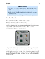
Страница 17: ...les on the screen in real time but does not store them provides feedback to help align successive sweeps in a scan and for filling in gaps reorients the display on the computer screen to a Wands s eye view illuminates the Laser LED shown in Figure 9 Figure 9 The Wand control panel with the power and Laser lights illuminated The secondary function of the Preview position is to reorient the on scree...

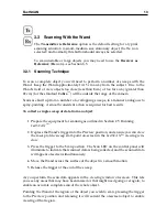
Страница 18: ...con or select View Camera View 2 Set the sensitivity control to position 1 3 Pull the trigger to the Preview position 4 Push the sensitivity control Up arrow to increase the sensitivity For the CobraTM the red curve of the laser profile should become visible For the ScorpionTM red and green curves should become visible the red curve is the laser profile as viewed by the bottom camera and the green...

Страница 19: ...t results To collect a single sweep of data from an object 1 Prepare the equipment for scanning as outlined in Section 2 5 Running FastSCANTM 2 Depress the Wand s trigger into the Preview position and ensure you can view the laser profile sweep start point on screen in the FastSCANTM viewing win dow 3 Press the trigger to the Scan position The Scan LED on the control panel will illuminate to indic...

Страница 20: ...ata and achieve the smoothest final surface avoid repeated scanning of the same part of a surface to reduce file size for large objects requiring many sweeps save your scan at regular intervals to prevent loss of scanned data You can erase the last sweep by clicking on Scanner Undo Sweep or by double click ing the Wand trigger see Section 3 4 Undoing Scans The erased sweep can be put back into the...

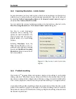
Страница 21: ...g Wireframe from the View menu will allow you to ex periment with different scanning speeds and Best Worst Scanning Resolution values to assess the ef fect on resolution Figure 10 The Scanner Limits Control dia log box 3 3 3 Profile Smoothing The FastSCANTM program filters and applies a degree of smoothing to each profile during collection This filter removes noise and errors in the scanner data b...

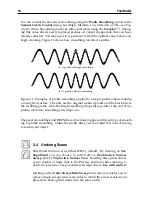
Страница 22: ...and the black line is the resulting profile Note that high smoothing drops three points at the end of the profile while low smoothing only drops one The generation of Basic and RBF Surfaces Section 4 applies a different type of smooth ing to profile smoothing Unlike the profile filter you can adjust this without having to rescan your object 3 4 Undoing Scans This Wand function is switched ON by de...

Страница 23: ...u must keep the Receiver at least 100 mm away from the Transmitter to avoid signal overload The subject can be rolled or rotated as required during scanning to enable full access for the Wand It is possible to remove the Receiver if required allowing you to scan the part of the object where it was attached Place the object and the Transmitter near to each other remembering that once you remove the...

Страница 24: ...ansmitter midway between the Receiver and the Wand As you move around the object also move the Transmitter keeping it within 100 mm and 750 mm of the Receiver and Wand Figure 13 Figure 13 Scanning a large T shaped object with Receiver as Reference R is the Re ceiver fixed to the object and T is the Transmitter moved around the object during scanning in positions 1 to 5 ...

Страница 25: ...sible scan Many of these functions can be performed via the keyboard Hotkeys See Section 9 1 for a full list Points Shows the individual data points that make up the scan Figure 14 a Wireframe Displays the surface triangular mesh created by linking the points data Figure 14 b Solid Displays the scanned object as a solid surface Figure 14 c Outlined Displays the object as a solid surface with the w...

Страница 26: ...he Bounding Box around the data and the exported data will be exported with the changed coor dinate system View View Bounding Box From enables viewing of the Bounding Box from other angles Front Back Top etc a Press F1 to get the view of the front of the Bounding Box b Use the movement keys or mouse to get this view Figure 15 The Bounding Box as seen from a the front b above and to the side The Ex...

Страница 27: ...ach incre ment Normals Clicking on View Normals will display the normals 90 to the object sur face of all the data points that make up the object Scanning Feedback Color Mapping The View Color Mapping options listed below display the object s surface in color highlighting optimum or poor parts of the scan Pseudo Grayscale displays a texture map based on the surface showing the ob ject in black and...

Страница 28: ... in out The magnification is displayed in the status bar at the bottom of the viewing window 3Dconnexion SpaceNavigator 3D Mouse FastSCANTM 4 0 7 onwards supports this mouse which is designed for use with 3D Software Once it s drivers are installed and the mouse connected it will work automatically The button on the left of the mouse centers the scanned object within the viewing window Users may f...

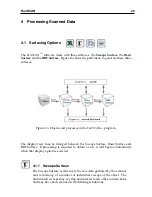
Страница 29: ...rogram The display view may be changed between the Sweeps Surface Basic Surface and RBF Surface If processing is required to obtain a view it will begin automatically when that display option is selected 4 1 1 Sweeps Surface The Sweeps Surface is effectively the raw data gathered by the scanner and is made up of a number of individual sweeps of the object The individual sweeps may overlap and inte...

Страница 30: ...Basic Surface with a Radial Basis Function RBF constructing an isosurface a mesh with evenly spaced points constraining the boundary of the RBF Surface in space simplifying the isosurface optional See the FastRBFTM Extensions Manual for more details regarding the RBF Surface 4 2 Export Format Surfaces can be exported in a variety of industry standard formats using the File Export As submenu this i...

Страница 31: ...t you cannot add more sweeps to them after exporting Save As To Save a scan under a new name or format click on File Save As or the Save As icon in the toolbar Scans can only be saved in the fsn and hls file formats Saved scans can be processed and exported but you cannot add more sweeps to them once exported Note If you want to export to a different format or to change the processing pa rameters ...

Страница 32: ... List dialog box shown in Figure 17 contains a list item for each sweep The second column gives the number of points in the sweep Figure 17 The Sweeps List dialog box To highlight a sweep best viewed with the Solid option click on it in the list Hold down Ctrl or Shift while clicking to select multiple sweeps The color of the high lighted sweep s in the main window will be changed to the preview c...

Страница 33: ...weep color this sweep is the only one covering this part of the surface Medium sweep color this sweep is on top but has other sweep s behind it Light sweep color this sweep is underneath other sweep s To hide a sweep uncheck the box to the left of the list item Hidden sweeps will not be displayed in the main window Hidden sweeps are ignored when processing and exporting but they are still saved by...

Страница 34: ...use to enclose the area you wish to delete To delete either select Edit Delete click on the Delete icon or use the Backspace key Be aware that you may be unwittingly selecting other sweeps behind the one you intended to edit e g the back of a scanned object To prevent this you may want to hide all of the sweeps other than the one to be edited by unchecking them in the left hand column in the Sweep...

Страница 35: ...ate Surface dialog box Figure 19 This enables the user to alter the characteristics of the Basic Surface before processing it 5 2 1 Smoothing When scanning you will probably scan some parts of the surface with multiple sweeps These sweeps may not always align perfectly Possible causes can include small errors in the scanner measurements metal objects interfering with the magnetic locater the objec...

Страница 36: ...weeps 5 2 2 Decimation Increasing the Decimation value in the Generate Surface dialog box Figure 19 re duces the number of points and triangles This means a smaller export file and sub sequently faster rendering of exported scans when loaded into other programs De creasing the value produces a more detailed mesh and a larger slower file Figure 22 shows the same object exported at two different dec...

Страница 37: ...nnot find a suitable value that merges sweeps while also preserving detail try the following Register the sweeps see Section 5 3 Delete the portion of the sweep s which is causing the problem Undo the sweep s over the problem area and re scan if necessary Re scan the object after removing metal objects from the scanning area Fix the object and the reference securely so that they cannot move during...

Страница 38: ...o remove these extra bits of surface but only if they are disconnected from and smaller than all the pieces of the main object Check the Limit Objects to box in the Generate Surface dialog Figure 19 and en ter the number of objects N that you wish to be preserved The export process will remove all the smaller objects leaving only the N largest If this method fails you can delete parts from the Swe...

Страница 39: ...ate the Basic Surface in the normal way and see if the RMS error has improved Figure 23 a shows an object with artifacts before Register Sweeps has been used and 23 b the improved result after it has been applied Occasionally Register Sweeps can cause deterioration in the quality of the Basic Sur face If the RMS error is larger after Register Sweeps has been applied choose Un register Sweeps from ...

Страница 40: ...meters if required Figure 24 shows the batch process ing dialog Select File Export As Batch Process to open the Batch Processing dialog On the left of the dialog is the list of scans to be processed If you currently have a scan open it will be placed in this list otherwise the list will be empty On the right of the dialog box are the controls for changing the settings of the se lected scan The upp...

Страница 41: ...al scans with the same settings configure the first scan before adding the rest if you want different surface settings for each file then be sure to edit them individually via the Generate Surface Settings box To remove a selected scan from the list click the Remove button Figure 25 The progress bar and message log displayed during batch processing Click the Run button to process and export each s...

Страница 42: ...RBF Surface See the FastRBFTM Extensions Manual for instructions on how to generate an RBF surface While an RBF surface may be generated with the unlicensed FastSCANTM software a license is required to enable saving of the surface ...

Страница 43: ...to work with your application program Scans can be exported with respect to the Screen Reference or Bounding Box coordi nate systems by selecting the appropriate option in the Coordinate System section of the File Export As dialog box Note you cannot reload any of these formats back into the FastSCANTM program When saving the Sweeps some file formats support saving each sweep as a separate object ...

Страница 44: ...e used to exchange many different types of data These files tend to be much larger than other export formats The FastSCANTM program can save three different types of IGES NURBS patch Entity 128 A triangle mesh with each triangle represented as a separate B spline surface This format is very inefficient and many programs may run out of memory when trying to load it Copious data Entity 106 A triangl...

Страница 45: ...s or triangle mesh in both binary or text formats The ply file can also be saved with optional vertex normal vectors or pseudo gray scale values Stereo Lithography stl A common format that supports triangle mesh The FastSCANTM program supports both text and binary stl files binary is faster and creates a much smaller file Virtual Reality Modeling Language wrl VRML is a scene description language c...

Страница 46: ...Snapshot Selecting File Save Snapshot creates a png screen image of the current data win dow Figure 26 Options with this function are available by selecting Save Snap shot Advanced including Crop to data Automatic file numbering and Append in formation text Figure 27 8 Help Clicking on the Help icon brings up the reference file for the FastSCANTM software also accessible through Help Software Refe...

Страница 47: ...FastSCAN 41 Figure 26 Example of a Saved Snapshot file Figure 27 The Save Snapshot dialog box with advanced options ...

Страница 48: ...7 View Set Bounding Box to View Ctrl B View View Bounding Box From Front F1 View View Bounding Box From Bottom F2 View View Bounding Box From Left F3 View Viewpoint Center Insert View Viewpoint Reset Home View Viewpoint Zoom In Page Up View Viewpoint Zoom Out Page Down View Viewpoint Rotate Left View Viewpoint Rotate Right View Viewpoint Rotate Up View Viewpoint Rotate Down View Viewpoint Roll Lef...

Страница 49: ...titioners to obtain high quality scans of the whole foot and lower leg while keeping them stable This is achieved by placing the feet on a raised pane of glass and scanning from beneath Click on Edit Refraction Correction and a dialog box will appear Fill in the infor mation boxes and click Do Normal commercial glass has a Refractive index of approximately 1 52 however this may vary for low lead o...

Страница 50: ...nctions Note Special Functions Available With The Stylus When in Laser Pointer Mode a double click of the Wand trigger will remove the last stylus point or line placed A triple click will remove all points lines As noted above these features can be enabled disabled under Settings Wand drop down menu 9 2 4 Export as AAOP OP3 object AAOP OP3 is a 3D file format supported by a number of orthotics and...

Страница 51: ... to a full factory calibration and it may not be possible to restore the scanner to its original condition if it has been badly misaligned To ensure that your FastSCANTM Wand stays in calibration always handle it with care Windows 2000 XP Note Under Windows 2000 or XP you will need Power User or higher privileges if you are going to perform a Calibration Correction 10 1 Overview To collect the dat...

Страница 52: ...beeps if the data is within the acceptable range as you scan the Calibration Target 10 2 Calibration Correction Procedure Perform the Calibration Correction as follows please read all the steps before begin ning 1 Set up the scanning environment as described in Section 2 5 It is imperative that you keep metal objects such as computers monitors and metal furniture at least one meter away from the s...

Страница 53: ...r beeping as you scan the Calibration Target 10 If the range was acceptable a red spot Cobra or red and green pair of spots Scorpion will appear on the screen 11 Rotate the Wand by 90 degrees and repeat step 9 Repeat this process two more times until you have scanned the target from all four sides Four spots Cobra or four pairs of spots Scorpion are collected at orientations of 0 degrees 90 degree...

Страница 54: ...or all data can be removed with a triple click These functions are switched on by default see Section 3 4 To help reduce artifacts the data is restricted to points within the vicinity of the Calibration Target it will not matter if you place the Transmitter and Target on a light colored surface Should the Transmitter already be bolted to a surface then the Calibration Target may be placed on the o...

Страница 55: ...enter of the sheet of paper so that the laser aperture faces downwards and the Wand lies across the width of the sheet 5 With the trigger pulled fully in lift the Wand vertically off the sheet at a constant rate Note the arrangement of Wand Transmitter and test paper as shown in Figure 31 6 Release the trigger once the laser line exceeds the width of the sheet 7 Press OK Figure 31 Procedure for pe...

Страница 56: ...Wand too close or too far away from the object while scanning preventing the camera from recording the movement of the laser Keep the Wand about 10 15 cm from the object when scanning Q My scanned image is upside down on the screen and I can t get it the right way up How can I fix this A The hemisphere of operation is not defined correctly Switch off the PU and switch it on again Then go through t...

Страница 57: ... keep them as close as possible Q When I generate a Basic Surface it has bumpy or crystalline patches what is wrong A Successive sweeps over the same part of the surface have not merged properly Try using Edit Register Sweeps Section 5 3 If the result is still unsatisfactory you may need to repeat the scan Q How far away do I have to keep metal objects from the scanner A The presence of metal obje...

Страница 58: ...s are grouped into different classes according to the degree of potential hazard they present Class 1 lasers are safe under any circumstances while the other Classes are not This laser is not a Class 1 laser The laser in this device has a Peak Power Output of 3 5 milliwatt at a wavelength of 670 nanometers It is a Class 3R Product in compliance with IEC 60825 1 2001 and a Class II Product in Compl...

Страница 59: ...ed to the Wand in the positions indicated on the following figures in Section 12 4 Warning La bels and Locations overleaf Caution Use of controls and adjustments or performance of procedures other than those specified in this manual may result in hazardous laser radiation exposure 12 3 Use for Medical Applications Polhemus is a Good Manufacturing Practices GMP Contract Manufacturer under U S FDA R...

Страница 60: ...g Labels and Locations a The Wand displaying warning labels b Warning labels c Close up of the laser aperture circled and two position trigger switch bottom d Wand control panel showing Laser On indicator light top right LED ...

Страница 61: ...qs com Brazil Absolut Technologies www abs tech com Canada AD3R Technologies www ad3r com China Beijing 6DOF Technologies Co Ltd Tech Trend International Ltd www 6dof com cn sales ttil com hk Croatia VR Logic www vrlogic com Denmark Finland Contact sales polhemus com France CADvisionS A S Immersion SA www cadvision fr Germany VR Logic EST Engineering Systems Technologies GmbH Co KG www vrlogic com...

Страница 62: ...anz com www fastscan3d com Portugal Aplein Ingenieros S A www apleiningenieros com NORCAM Engenharia E Design Industrial LDA www norcam pt norcam index html Singapore Interactive Dreams Pte Ltd www id dreams com 020115 044 welcome frame htm Spain Aplein Ingenieros S A www apleiningenieros com Sweden Contact sales polhemus com Switzerland EST Engineering Systems Technologies GmbH Co KG www est kl c...

Страница 63: ...ntainer for your FastSCANTM system in the event that the instrument may require repair Please do not return any instrument without an RMA number as it will not be accepted If your instrument is still under warranty Polhemus will repair it free of charge according to the provisions of the warranty as stated in Section 15 of this document The proper return shipping address is Polhemus 40 Hercules Dr...

Страница 64: ... the direction of Polhemus Customer Service ship such parts to Polhemus Upon determination by Polhemus that the parts or Systems are defective and covered by the warranty set forth above Polhemus at its option shall repair or replace the same without cost to Buyer Buyer shall pay all charges for transporta tion and delivery costs to Polhemus factory for defective parts where directed to be sent to...

Страница 65: ... SPECIFICALLY DISCLAIMS THE WAR RANTY OF MERCHANTABILITY OF THE PRODUCTS OR THE WARRANTY OF FITNESS OF THE PRODUCTS FOR ANY PARTICULAR PURPOSE POLHEMUS MAKES NO WARRANTIES EXPRESS OR IMPLIED EXCEPT OF TITLE AND AGAINST PATENT INFRINGEMENT OTHER THAN THOSE SPECIFICALLY SET FORTH HEREIN 15 7 IN NO EVENT SHALL POLHEMUS BE LIABLE UNDER ANY CIRCUMSTANCES FOR SPECIAL INCIDENTAL OR CONSEQUENTIAL DAMAGES ...

Страница 66: ...e lease or sell as appropriate such product or part or b replace such product or part or c modify such product or part or d remove such product or part and refund the aggregate payments and transportation costs paid therefore by the Buyer less a rea sonable sum for use damage and obsolescence Polhemus shall have no liability for any infringement arising from i the combination of such product or pa...

Отзывы: