Version: 20220420
19
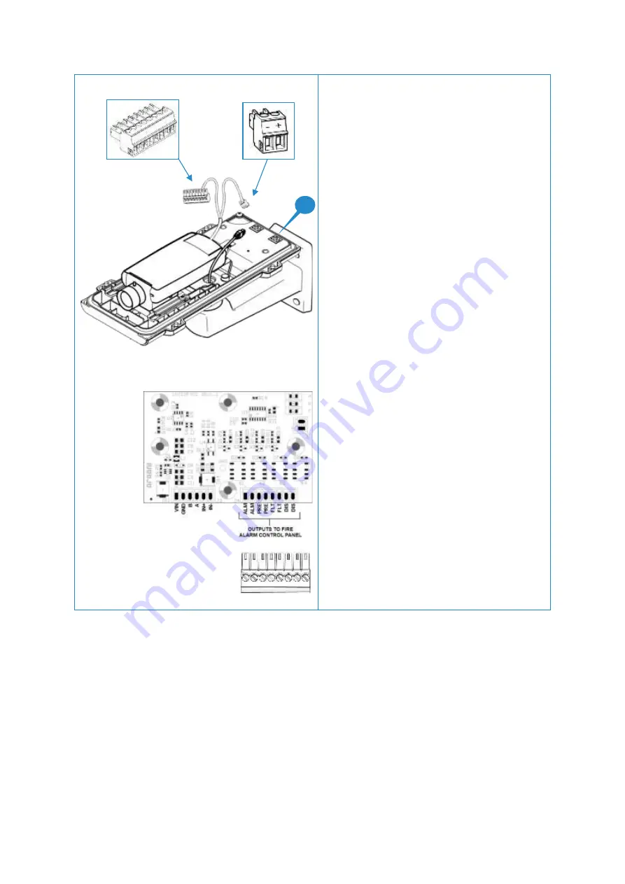
5 Connect power and alarm wires
Strip the outer isolation of the power/alarm cable for
about 15 cm.
Separate the 2 power wires from the alarm wires.
Attach the 2-pins power mating connector to the
power wires and fit it to the power connector of the
camera housing
.
Attach the alarm wires from the power/alarm cable
to the 8-pins mating connector of the interface board.
Consult the connection diagram on the left for
identification. Connector labels correspond to
outputs as follows:
ALM = Output 1, default configuration = alarm
(configurable) (Normally Open)
PRE = Output 2, default not used (configurable)
(Normally Open)
FLT = Output 3, fixed fault (Normally Closed)
DIS = reserved for future use
Consult the manual of your fire alarm control panel to
determine the appropriate wiring. This may involve
the use of resistors to combine alarm, fault and other
signals.
Attach the 8-pin I/O connector to the interface board.
1


