background image

AQM-550 Manual Version 1.2


Page 8


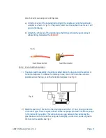
Attach Feed Water Adaptor to RO System:


a)


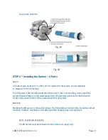
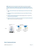
Attach one end of the included red tubing to the needle valve on the feed water 
adaptor as shown in 

Fig. 5c.

 The plastic insert must be pushed in as far as it will 

go into the tubing.


b)


Attach the other end of the red tubing to the RO System on the quick connect 
elbow fitting, marked with a 

RED


DOT.


Part 2:   Drain Saddle Installation  

1)


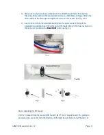
The drain saddle assembly should be installed above the trap and on the vertical or 
horizontal tailpiece. To reduce the drainage noise, mount the drain line as low as 
possible above the trap, or on the horizontal tailpiece.

See Fig. 6


2)


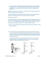
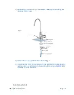
Mark the position of the hole on the drain pipe and drill a 1/4’’ hole through one side 
of the drain pipe. There is a piece of self-adhesive sponge provided. Stick this sponge 
to the inside of the saddle. This will cushion any gap between the saddle and the 
pipe. Make sure the hole on the sponge is thoroughly punched out, and is aligned to 
the hole on the saddle. 

See Fig. 7


Содержание AQM-550

Страница 1: ...AQM 550 Manual Version 1 2 Page 1 ...

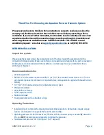
Страница 2: ...ing is damaged during shipping If any part is cracked or broken please do not proceed with the installation Contact Aquatron or your distributor for an exchange or diagnosis Recommended tools list Variable speed drill Drill bit for the waste line drain saddle or 7 16 for standard Faucet Hole or 1 1 4 for air gap faucets optional or wherever it is required by law call Aquatron to upgrade the faucet...

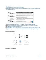
Страница 3: ...y has a high content of iron or rust an iron filter is recommended If the water supply contains bacteria we recommend adding an ultra violet sterilizing filter DO NOT connect this unit to hot water source Install the RO in a sheltered environment Avoid exposure to hot and cold weather direct sun light Note Warranty on this system is dependent on proper maintenance and yearly filter changes Compone...

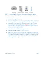
Страница 4: ...ply first enters The elbow fitting with the RED DOT label is attached to this housing Note The sediment filter is slightly longer than the two carbon filters due to the way it seals with the inner ring of the canister 4 Put the carbon filter into the 2nd stage housing in the middle 5 Put the other carbon filter into the 3rd stage housing on the left 6 Starting from the 3rd stage housing on the lef...

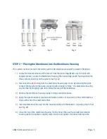
Страница 5: ... Do so by releasing the quick connect fitting refer to the quick connect guide on page 3 Note the membrane housing cap has been left slightly open to facilitate this step of the installation 3 Remove the membrane housing cap by turning counterclockwise 4 Apply food grade lubricant available in hardware stores or Aquatron to the small double o rings at the end of the membrane filter 5 Insert membra...

Страница 6: ...that is not feasible you can install the system anywhere there is a cold water supply with sufficient water pressure for the chosen RO model and an outlet to drain off the waste water from the system Mounting Mounting the RO system to the wall is optional The RO system can stand in the sink cabinet without mounting However mounting it can make future filter changes easy and convenient Part 1 Feed ...

Страница 7: ...r pipe The needle valve portion screws onto the adaptor as shown in Fig 5 The cone shaped washer provided is optional If your pipe already has a built in cone washer then no need to use this one if it is in good condition See Fig 5 2 Apply 7 turns of Teflon tape to the threaded end of the needle valve and screw it onto the feed water adaptor 3 For Flex Line Riser Loosen nut and separate cold water...

Страница 8: ...n 1 The drain saddle assembly should be installed above the trap and on the vertical or horizontal tailpiece To reduce the drainage noise mount the drain line as low as possible above the trap or on the horizontal tailpiece See Fig 6 2 Mark the position of the hole on the drain pipe and drill a 1 4 hole through one side of the drain pipe There is a piece of self adhesive sponge provided Stick this...

Страница 9: ...evenly See Fig 8 8A 4 Insert one end of the included black tubing into the quick connect fitting of the installed drain saddle Insert the other end of the black tubing to the flow restrictor on the main unit marked with a BLACK DOT label See Fig 6a Part 3 Installing the RO Faucet Drill 1 2 diameter hole for standard RO faucet 1 1 4 hole if air gap faucet For granite or porcelain sinks we recommend...

Страница 10: ...t convenient for dispensing pure water An ample flat area is required for the faucet base so that the faucet can be drawn down tightly Faucet location Make sure the faucet stud will be accessible from below when the hole is drilled If space is not available on the upper sink area the faucet can be located on the counter top by the edge of the sink If the counter top is ceramic tile the method for ...

Страница 11: ...AQM 550 Manual Version 1 2 Page 11 Mounting the Faucet ...

Страница 12: ... the sleeve then the insert 2 Screw on the blue tubing to the faucet as shown in Fig 9 3 Connect the other end of the blue tubing to the final polishing filter located above the membrane housing The fitting on the final polishing filter also has a BLUE DOT label to indicate the faucet connection Part 4 Hook up the Tank ...

Страница 13: ...ply 10 turns of Teflon tape to tank s threaded output stem and screw on the tank ball valve 2 Attach one end of the included white tubing to the quick connect fitting of the storage tank valve 3 Attach the other end of the white tubing to the remaining port of the T Fitting which is attached to the final polishing filter 4 Gently place the tank in its final location and continue to the next step f...

Страница 14: ...The tank works fine in this position If the tank cannot fit under the kitchen sink it can be placed elsewhere up to 20 feet away from the RO system but this could result in lower pressure to your drinking water faucet 3 Call Aquatron if you would like to add an optional ice maker line to your reverse osmosis system Otherwise disregard the icemaker t fitting in the diagram Step 5 System Startup ...

Страница 15: ...down to drain tank this takes about 5 minutes Let the tank refill again 2 4 hours Drain tank one more time and the pure water is ready for use once it refills Note The first few cycles will most likely contain black residue from the final polishing filter This is the filter s natural carbon particles and will be permanently flushed out after completing this step 5 Clean up area Allow the system to...

Страница 16: ... of the canisters 5 Re apply food grade lubricant to the o rings inside the canisters making sure they are free of debris 6 Place the new filters inside each filter housing 7 Tighten housing canisters back on by hand then use the wrench to turn no more than a turn For the membrane 1 Remove the tubing from the membrane quick connect fittings 2 Use pliers to pull the membrane out of the membrane hou...

Страница 17: ...eed water pressure to the unit is no less than 45 PSI 30 PSI for systems with a booster pump and no greater than 80 PSI The system is to be used on water supplies with chlorine concentrations of 1 0 mg L or less Feed water temperature to the unit must be no less than 40 F and no more than 100 F Total dissolved solids TDS in feed water must be less than 750 mg L ppm Feed water must have a pH betwee...

Страница 18: ...stage travel telephone expenditures or other losses of this nature In case some states do not allow the exclusion or limitation of incidental or consequential damages you may choose to return the system If you choose to keep it you insist this exclusion STILL applies to you Owner s warranty responsibilities As a condition of this warranty the owner must ensure periodic maintenance of the system is...

Отзывы: