4
To maintain your UV units warranty, please fill out
and mail the Warranty Registration Card in the back
pocket of this manual to Aquafine Customer Service.
The following installation and operating conditions are
considered hazardous or damaging to the equipment
and can compromise the ability of the Aquafine unit to
perform as intended.
ANY OF THE FOLLOWING CONDITIONS WILL
VOID THE EQUIPMENT WARRANTY.
1. Failure to connect proper electrical service to unit.
2. Failure to properly ground the unit.
3. Failure to eliminate excessive vibration, piping
movement, or water hammer.
4. Failure to exercise caution in the handling of the
sensitive and delicate components (such as lamps,
quartz sleeves, electronic boards, etc.) during
installation and/or maintenance procedures.
5. Failure to avoid excessive stops and starts. Not more
than three (3) on/off cycles per 24 hours of operation.
6. Operation of visibly damaged equipment.
7. Failure to avoid undue overhead piping stress which
can result in structural damage to the UV unit.
Limit the load to 10 lbs (4.54kg) per flange.
8. Use of components other than those provided or
authorized by Aquafine.
9. Failure to correct overhead piping connection leaks
or compression nut seal leaks which result in
damage to the electrical components.
10. Operating the unit without water flow.
SL series
The SL Series is the appropriate choice for many low
volume indoor applications because it offers a compact
footprint and easy installation. All three models
combine the electrical components and the treatment
chamber in one integral unit.
SL-10A
This unit mounts vertically. Inside the cabinet housing
are the ballast and the UV treatment chamber. The
housing has a front cover which allow access to all
interior components. On the side of the treatment unit is
a knockout for electrical input power.
SL-1
This unit mounts vertically. Inside the cabinet housing
are the ballast and the UV treatment chamber. The
housing has a front cover which allows access to all
interior components. On the side of the unit is a
knockout for electrical input power.
MP-2-SL
This unit mounts horizontally. Inside the electrical
housing are the ballast and two UV treatment chambers.
They operate serially, as this is the most efficient
design. The housing has a front cover which allows
access to all interior components. On the back is a
knockout for electrical input power.
treatment chamber
On both ends of the UV treatment chamber are gasketed
end plates which contain the stainless steel nipples,
compression nuts, O-rings and lamp socket retainer
assemblies. (This option is for RA finish cylinders).
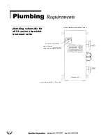
Each treatment chamber is fitted with two raised-face
stainless steel flanges (in the case of the MP-2-SL, each
chamber has one flange each). The bottom flange is
always designated as the inlet, while the top flange is
the outlet.
Inside the inlet flange is a helical baffle that prevents
laminar flow and maximizes the unit’s performance.
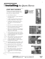
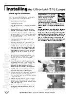
The quartz sleeves fit inside the UV treatment chamber
through the threaded nipples. The UV lamps fit inside
the quartz sleeves. The lamp sockets connect to the
lamps, providing a waterproof seal and a vibration-proof
grip.
Содержание MP-2-SL
Страница 2: ......


