background image

© 2008 Aqua-Hot

®

 600-D Hydronic Heating System Installation Manual

— Page 34 —

section 9: Electronic Controller Wiring


1.

  Calculate the necessary wire gauge for the 12 Volt-DC 

power and ground wires.


A.  

Determine the total maximum amperage draw of  

the Aqua-Hot heating system by adding the total 

maximum Amps of  the installed heat exchang-

ers (consult the heat exchanger manufacturer for 

Amp-draw information) to the Aqua-Hot heater’s 

22 Amps.

NOTE: 

Each heating zone “FAN” circuit can supply up to 

2.0 Amps of  direct current.  Each Aqua-Hot Cozy 

heat exchanger draws .23 Amps of  direct current.

For example, an Aqua-Hot heater with six Aqua-

Hot Cozy heat exchangers draws a total of  23.38 

Amps ((6x.23)+22).

B.

   Determine the total length of wire required to 

connect the Electronic Controller to the vehicle’s 

battery.

C. 

  Reference Appendix B with the total Amps and 

length of  wire to determine the necessary wire 

gauge.  For example, an Aqua-Hot heater with 6 

Aqua-Hot Cozy heat exchangers with the Elec-

tronic Controller placed 15 feet from the vehicle’s 

battery would require an 8-gauge wire.


2.

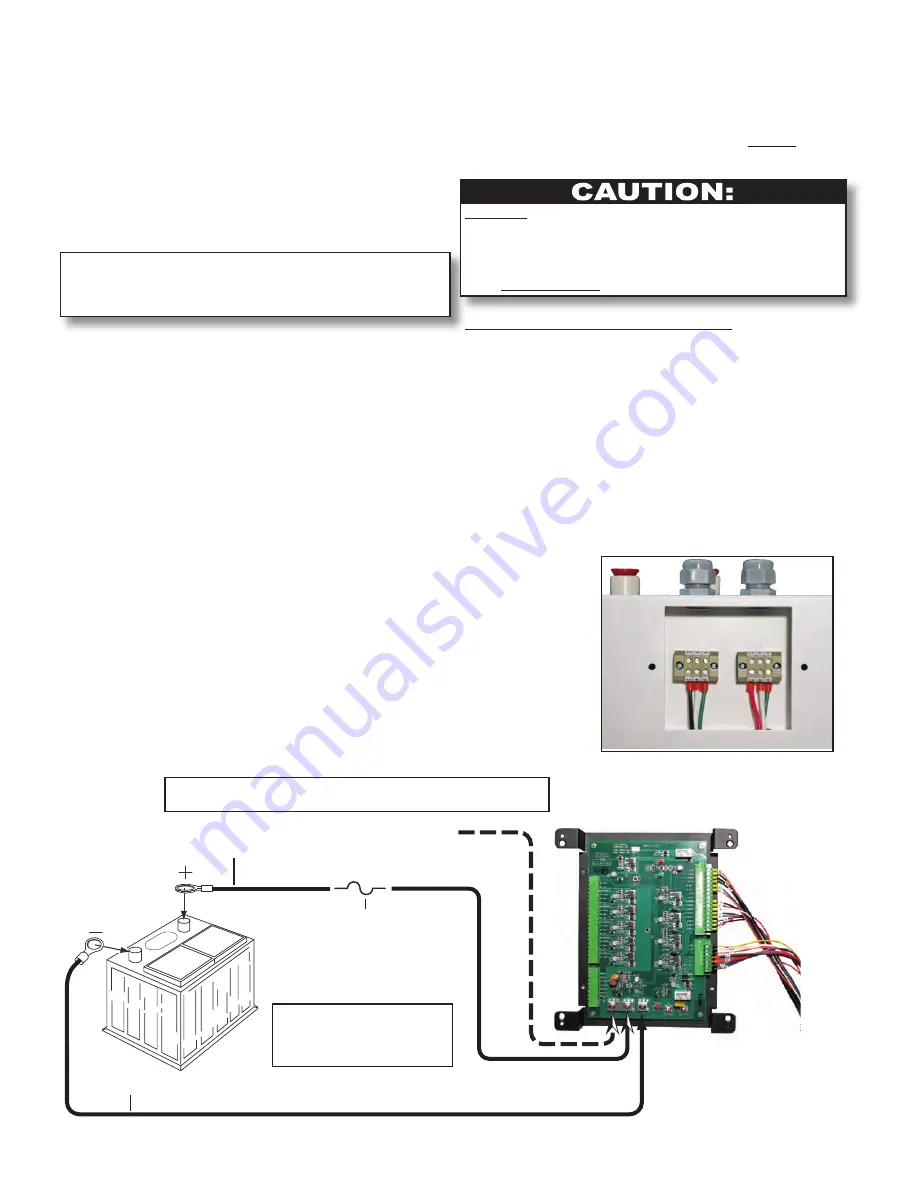
  Run and connect two wires –– one red (+) wire and 

one black (-) wire (power and ground), from the ve-

hicle’s battery to the Aqua-Hot’s electronic controller.  

Reference Appendix A and Figure 45.


3.

  Label the wires indicating whether they are a power or a 

ground wire.


4.

  Attach the DC power wires onto the appropriate ter-

minal/battery connections on the electronic controller.  

Reference Appendix A.


5.

  Connect both power and ground wires 

directly 

to the 

vehicle’s batteries.

DO NOT 

activate the diesel-burner until the antifreeze and 

water heating solution has been added to the boiler tank and the 

heating system has been completely bled of air.  Operating the 

Aqua-Hot without the antifreeze and water heating solution will 

cause 

serious damage

 to the Aqua-Hot’s boiler tank.

Connecting the 120 Volt-AC Power:

1.

  Route and insert three 120 VAC power source wires 

into the terminal block access area through the ap-

propriate port’s cable clamp fitting and into the proper 

terminal.  Reference Appendix A and Figure 44.

2.

  Secure the wires into their terminals by tightening the 

corresponding screw on the terminal block.

3.

  Re-install the terminal block access cover and tighten 

the screws securing the cover to the Aqua-Hot.

Optional connection to the 

house battery disconnect

In-line

Fuse

Positive/Power

Negative/Ground

NOTE:

  Reference Appendix A 

for specific electronic 
controller wiring 
details.

NOTE:

  If the optional power connection is used, remove the jumper 

plate from the two power terminals - “JP5” and “JP8.”

Figure 44

Figure 45

Содержание 600-D

Страница 1: ...2008 Aqua Hot Heating Systems Inc Installation Manual...

Страница 2: ...quirements 10 Mounting the Heat Exchangers 11 Wiring the Heat Exchangers 13 Plumbing Requirements 14 Plumbing the Hydronic Heating System 15 Section 3 Thermostats Fresh Water Tank Thermostat Location...

Страница 3: ...9 Electronic Controller Wiring Electronic Controller Wiring 32 Wiring Harness Connection 33 Connecting the 12 Volt DC Power 33 Connecting the 120 Volt AC Power 34 Section 10 Purging the Systems Purgin...

Страница 4: ...ures 1 through 5 for a complete component overview Please note that all Danger Warning Caution and Note boxes appearing as needed throughout this manual must be reviewed and adhered to during the in s...

Страница 5: ...lectric Heating Element specifications 2 120 Volt AC 2000 watts Zone Heat Circulation Pump specifications 3 12 Volt DC 21 watts each Number of Heating Zones maximum of 5 plus Engine Preheat Domestic W...

Страница 6: ...600 D Hydronic Heating System Installation Manual Aqua Hot Hydronic Heating System Wiring Harness Domestic Water Access Panel Drain Valve Diesel Burner Interlock Switch Diesel Burner Controller 30693...

Страница 7: ...ness Port Figure 4 Expansion Tank Connection Air Release Valve Heating Zone Outlet Port 2 Heating Zone Outlet Port 1 Engine Preheat Ports Heating Zone Inlet Ports VAC Wiring Ports Domestic Water Ports...

Страница 8: ...5 Cut Out 17 99 Cut Out 17 48 Center of Holes 17 48 Center of Holes NOTE All measurements are in inches Motorhome Floor Outline of Mounting Tray Additional Cross Member for Support may be necessary CU...

Страница 9: ...a Hot prior to placement into the installed mount ing tray Reference Figure 9 Be sure to provide an adequate support system for the mounting tray if adequate support is not present a cross member will...

Страница 10: ...Page 7 2008 Aqua Hot 600 D Hydronic Heating System Installation Manual Side View Front View NOTE All measurements are in inches Top View Bottom View 2 0 1 30 Section 1 Aqua Hot Installation Figure 9...

Страница 11: ...stem Installation Manual Page 8 Access Cover Combustion Air Sleeve Mounting Tray Flange Mounting Tray Aqua Hot 600 D Access Cover Section 1 Aqua Hot Installation Mounting Tray Flange Aqua Hot 600 D Ta...

Страница 12: ...1 NOTE Avoid any dips and bends in the overflow tubing from the Aqua Hot to the expansion tank as air can become trapped in these dips and bends preventing the expan sion of the heating solution from...

Страница 13: ...rance information NOTE An accessory device is available for the Cozy Heat Ex changer for the purpose of redirecting the airflow from the heat exchanger Reference Figure 16 Mounting Requirements Suffic...

Страница 14: ...tem Figure 17 Mounting the Heat Exchangers 1 Cut out a 2 5 inch H x 10 inch W opening for each heat exchanger outlet and cold air return register Reference Figure 15 2 Mount each heat exchanger perman...

Страница 15: ...Hydronic Heating System Vertical Mount Horizontal Mount Mounting Tab Figure 18 3 500 in 5 50 in 1 06 in 0 38 in 2 812 in 6 500 in 10 500 in 13 687 in 6 44 in 13 06 in 14 44 in NOTE Tolerances on the...

Страница 16: ...tronic control ler Reference Figure 21 and Appendix A 4 Wire all heat exchangers in the same zone in series 5 Connect all electronic controller wires to the positive and negative leads of the heat exc...

Страница 17: ...ating Loop 3 Reference Figure 22 The fresh water tank and bathroom heat exchangers typically 3 must be plumbed together in series on Heating Loop 2 Reference Figure 22 The bedroom heat exchanger must...

Страница 18: ...sest heat exchanger for both heating loops Reference Figures 23 and 24 Then connect each additional heat exchanger in the same arrangement low to high Reference Figure 22 4 Connect and clamp the inlet...

Страница 19: ...stant Tension Clamps Pex Insert Pex Insert Outlet Inlet 5 8 inch I D 3 4 inch O D 5 8 inch I D 3 4 inch O D Automotive Type Rubber Heater Hose Coupler 3 4 inch I D Automotive Type Rubber Heater Hose C...

Страница 20: ...ing Loop 3 Outlet Plumbing Port Inlet Plumbing Port Outlet Heating Loop Ports Inlet Heating Loop Ports Constant Tension Clamps Heating Loop 2 Outlet Plumbing Port Heating Loop 1 Outlet Plumbing Port H...

Страница 21: ...location for the thermostat based upon the previous location information 2 Once the thermostat has been completely wired permanently mount the thermostat in place Reference Figure 26 6 0 10 20 30 0 0...

Страница 22: ...l interior room thermo stats Room Thermostat Wiring 1 Run two 18 gauge wires from each room thermostat mounting location to the Aqua Hot s electronic con troller Reference Appendix A NOTE It is recomm...

Страница 23: ...water using fixture when computing pipe sizes NOTE As stated directly from the ANSI A119 2 NFPA 501C Standard on Recreation Vehicles 1993 Edition Piping Systems shall be sized to provide an adequate...

Страница 24: ...te directional flow of domestic water To Hot Water Faucets Domestic Hot Water OUTLET Fresh Water Storage Tank Domestic Cold Water INLET To Cold Water Faucets Demand Pump AT Indicates options for mount...

Страница 25: ...70 as well as the regulation of authorities having jurisdiction and CSA Standard B139 Figure 30 Switch Panel Mounting 1 Cut out an opening for the switch panel plate The Aqua Hot 600 D requires a 5 i...

Страница 26: ...oller Pin 1 Pin 3 Pin 5 to Diesel O to Diesel I to IND LT B6 Pin 4 to IND LT B3 Jumper Wire Jumper Wire Jumper Wire to 1 Way Plug Switch Panel Wiring 1 Run 16 gauge wires from the switch panel to the...

Страница 27: ...cations Also be sure to reference the ANSI NFPA 1192 hand book for information regarding fuel distribution system specifications Fuel head pressure should not exceed 10 feet Refer ence Figure 33 Use a...

Страница 28: ...ary and apply protective shielding in areas where chafing may occur 50 ft maximum distance 50 ft maximum distance Maximum Allowable Suction Height 7 feet Figure 34 3 Label both fuel lines indicating w...

Страница 29: ...Figure 34 Output to the Aqua Hot s Fuel Inlet Port Reference Figure 36 TOP VIEW of Fuel Filter Head Fuel Filter Input from Fuel Tank Fuel Pick Up Pipe reference Figure 27 Output to the Aqua Hot s Fue...

Страница 30: ...s Secure both plumbing lines where necessary and apply protective shielding in areas where chafing may occur NOTE Rubber coated closed type clamps are recommended when securing the plumbing lines Use...

Страница 31: ...POTENTIAL OUTLET PORT pressure outlet port Ideal Return Port T ToTTop side of the engine Hose Clamp Automotive Type Heater Hose Automotive Type Heater Hose Hose Clamp M NPT by Hose Barb To the Aqua Ho...

Страница 32: ...e exhaust pipe cannot be longer than 20 feet The two black pipe exhaust fittings MUST be utilized with all installations Failure to conform could create a hazardous situation and will void the Aqua Ho...

Страница 33: ...type exhaust piping and avoid bends if possible Reference Figure 39 A maximum of two 90 exhaust pipe bends are al lowed Reference Figure 39 Do not use galvanized pipe or fittings only black iron pipe...

Страница 34: ...ple Mounting Tray Flange Exhaust Pipe Elbow Depth of Motorhome Bay Floor Figure 41 Installing the Exhaust System 1 Run the exhaust pipe to the driver s side of the vehicle and ensure that the exhaust...

Страница 35: ...Therefore be sure to use care when wiring these particular components to the electronic controller Each heating zone FAN circuit can supply up to 2 0 Amps of direct current This 12 Volt DC power sourc...

Страница 36: ...Connection 1 Attach the wiring harness connectors to the electronic controller Reference Figure 43 and Appendix A 2 Tighten the screw type fasteners on the terminal strips to secure them to the elect...

Страница 37: ...Hot s electronic controller Reference Appendix A and Figure 45 3 Label the wires indicating whether they are a power or a ground wire 4 Attach the DC power wires onto the appropriate ter minal battery...

Страница 38: ...drain valve located at the front of the heater Reference Figure 46 2 Connect a piece of inch PEX tubing this piece should be long enough to be used to transport the antifreeze and water heating soluti...

Страница 39: ...urce NOTE The circulation pump will activate as soon as the pump is connected to a ground source therefore disconnect the alligator clip from the ground source during the antifreeze and water heating...

Страница 40: ...vent the Aqua Hot from operating whenever the main access cover is not properly installed 2 Move the diesel burner switch to the ON position for approximately ten seconds ONLY then switch it OFF NOTE...

Страница 41: ...2008 Aqua Hot 600 D Hydronic Heating System Installation Manual Appendix A Wiring Diagram Appendix A...

Страница 42: ...2008 Aqua Hot 600 D Hydronic Heating System Installation Manual Page A 1 Appendix A Wiring Diagram...

Страница 43: ...Appendix B Appendix B Wire Gauge Information...

Страница 44: ...0 3 0 4 0 4 0 4 0 4 0 50 6 6 4 4 2 2 1 0 2 0 2 0 3 0 3 0 4 0 4 0 4 0 60 6 4 4 2 2 1 0 2 0 3 0 3 0 4 0 4 0 4 0 70 6 4 2 2 1 0 2 0 3 0 3 0 4 0 4 0 80 6 4 2 2 1 0 3 0 3 0 4 0 4 0 90 4 2 2 1 0 2 0 3 0 4 0...

Страница 45: ...Appendix C Appendix C Electronic Controller Features...

Страница 46: ...y connection will ensure completion of the required 3 minute purge cycle of the Aqua Hot s diesel burner NOTE This illustration details the proper wiring requirements for the usage of the battery disc...

Страница 47: ...ic controller use a thin straight nonmetallic object to access the button through the faceplate or by turning OFF the diesel burner switch on the interior switch panel for approximately 30 seconds the...

Страница 48: ...Appendix D Appendix D Antifreeze Types...

Страница 49: ...specifically for winterizing appli cations only Although RV Marine antifreeze is often Generally Recognized as Safe by the FDA it should never be used in the Aqua Hot s Hydronic Heating System This t...

Страница 50: ...Appendix E Appendix E Antifreeze Mixture Water Quality Recommendations...

Страница 51: ...ifreeze with water suppliers of pre mixed antifreeze are responsible for the use of high quality distilled de ionized or soft water when preparing their antifreeze for sale Hard water possesses a high...

Страница 52: ...Appendix F Appendix F Antifreeze Terms and Mixture Ratio...

Страница 53: ...ling point is reached a loss of efficiency occurs because the heat produced is expelled rather than utilized for the function of the heating system Therefore a higher boiling point is desired in order...

Страница 54: ...stallation Manual Page F 2 Appendix F Antifreeze Terms and Mixture Ratio 10 0 20 40 60 20 30 10 20 30 40 50 60 Freezing Point Temperature In Degrees Fahrenheit l o c y l G e n e l y p o r P f o e g a...

Страница 55: ...15549 East Highway 52 Fort Lupton Colorado 80621 1 800 685 4298 Fax 303 857 9000 www aqua hot com...

Отзывы: