ENGLISH
48
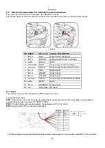
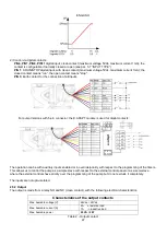
The functions that can be activated on the output contact are described in paragraph 5.4.
To connect to the input and output connector, use only the cable kit. The details of the connector and of
the connection are included in the kit.
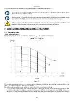
Attention: keep the cable for the input and output signals well away from the power and alternate supply
lines (230V and similar), so as to limit disturbances and interference that can alter the signals.
When it is not in use, the connector on the pump must be kept accurately closed, with the cap well
tightened. Only in this way is the necessary resistance to water and damp guaranteed.
3 SWITCHING ON AND USING THE PUMP
3.1 Operating mode
3.1.1 Regulating modes
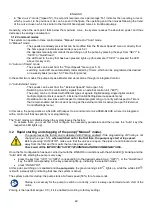
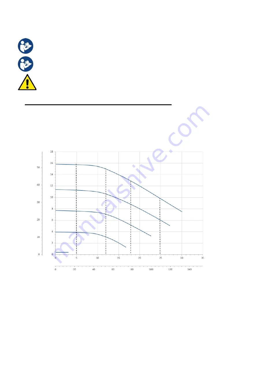
The following diagram shows the indicative curves of the system’s hydraulic performances.
PRIME E-SILENCE VS
Head H
ft m
m
3
/h
US GPM
Flow Q
Figure 11
The inverter automatically regulates the rotation speed of the pump, shifting the work point, as necessary, to any part
of the area subtended by the maximum curve (100%).
Regulation during pumping can takes place in
flow control
mode or in
fixed curve
mode.
-
In
“flow control”
(“Flow”)
the system assesses the instantaneous flow of water and varies the pump speed so that
the flow corresponds to the setpoint, expressed in this case in “
m
3
/h
” (cubic metres per hour) or “
GPM
” (US gallons
per minute). In this mode, the work point moves (ideally) on a vertical line, corresponding to the flow value chosen.
20
%
50
%
70
%
85
%
100%

