WAFER PATTERN CHECK VALVES - ‘SLP’ & ‘SW’ STYLE
Australian Pipeline Valve - Installation, Operation and Maintenance Manual
8
2.9 GASKETS
The opening end of the outlet side of Single Flap Check valve is manufactured larger than the internal
diameter of the pipe. Use a gasket that is either the same internal diameter of the Uni-Check outlet, or
slightly larger. Most common spiral wound or CNAF pipe gaskets will fit, providing they are the same
corresponding flange class rating as the valve it’s specified to. CNAF gaskets are only suitable up to 1400
kPa (200 PSI). Ring joint gaskets are frequently specified for class 900 to 2500. The recommended
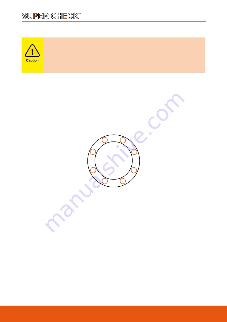
tightening sequence is shown below in Diagram 4. Tighten in numerical order, gradually increasing torque
with each sequence.
2.10 POST-INSTALLATION PROCEDURES
After installation, the line should be cleaned by flushing to remove any foreign material. When caustics
are to be used to flush the line, additional flushing with clean water is required. The valve should be
opened and closed after installation to ensure proper operating function.
With the line pressurised, check the valve end connections and any body plugs for leaks.
3 . 0 O P E R A T I O N
The check valve operation is automatic and requires no assistance. When the flow exerts sufficient
pressure against the disc to overcome the disc’s weight, the disc allows the flow to continue through the
piping system. As pressure decreases, the disc lowers until it’s own weight forces it to seat. This prevents
the possibility of a reversal in the flow. Metal seated check valves are not zero leak devices and may
Wafer check valves are designed for steady flow conditions and are not
recommended for use near reciprocating pumps, but especially compressors, any
pulsating devices or other types of physical/thermal shock-load applications. In this
type of application, the check valve will not perform efficiently and will ultimately
fail.
3
8
2
5
4
7
1
6
ORDER OF TIGHTENING BOLTS
DIAGRAM 4


