2–23
PacketMax 5000 Installation and Operation Manual, 10007678 Rev J
Chapter 2. Base Station Components
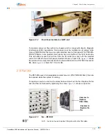
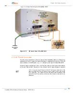
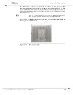
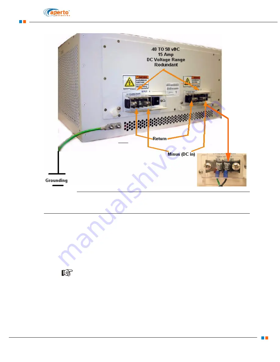
shows the AC input in PacketMax 5000.
Figure 2-16
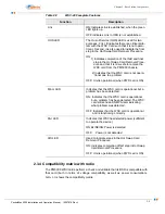
DC input- Rear of the PM 5000
2.13 AC Power Connection
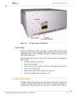
The AC power connection on the rear panel of the PacketMax 5000 is a three-prong
standard port for AC power that accommodates a standard IEC 320 plug. This port
also contains an On/Off switch.
shows the AC input in PacketMax 5000.
If two AC power supplies are in use, only then the users can have power redundancy.
In the case that one AC chassis is in use, at least one AC power supply is required.
NOTE:
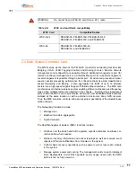
If you are using DC power to the BS, both power connectors on the
back of the BS have to be connected to power outlets for the power supply
to be redundant. The chassis has two redundant power backplanes and
each of the two DC connectors on the back of he chassis is connected to one
backplane.
Содержание PacketMAX 5000
Страница 10: ...Preface Preface vi PacketMax 5000 Installation and Operation Manual 10007678 Rev J ...
Страница 14: ...Table Of Content TOC 4 PacketMax 5000 Installation and Operation Manual 10007678 Rev J ...
Страница 38: ...1 20 PacketMax 5000 Installation and Operation Manual 10007678 Rev J Chapter 1 Overview Of Base Station ...
Страница 64: ...2 26 PacketMax 5000 Installation and Operation Manual 10007678 Rev J Chapter 2 Base Station Components ...
Страница 104: ...5 16 PacketMax 5000 Installation and Operation Manual 10007678 Rev J Chapter 5 Commissioning the Base Station ...
Страница 114: ...A 10 PacketMax 5000 Installation and Operation Manual 10007678 Rev J Chapter A Event Reporting ...
Страница 124: ...C 6 PacketMax 5000 Installation and Operation Manual 10007678 Rev J Chapter C Cables Spares and Accessories ...
Страница 146: ...E 4 PacketMax 5000 Installation and Operation Manual 10007678 Rev J Chapter E Certifications ...
Страница 150: ...F 4 PacketMax 5000 Installation and Operation Manual 10007678 Rev J Chapter F Troubleshooting ...

