2–14
PacketMax 5000 Installation and Operation Manual, 10007678 Rev J
Chapter 2. Base Station Components
2.5 MSC Redundancy
The MSC Redundancy feature prevents the MSC from becoming a single point of
failure. This also reduces system downtime due to replacement of MSC cards. This
feature requires that a second MSC card is installed in to the PM 5000 BS.
The configuration uses a secondary card of the same type to serve as a standby card
and takes over if the active card fails. In this 1:1 redundant card configuration, one
card operates in the active mode and a second card operates in standby mode, ready
to provide services if an active card fails. To minimize switchover time and prevent
service interruption, standby cards are dedicated to a single active card and cannot
support additional cards. Standby cards do not support services until they transition
to the active state.
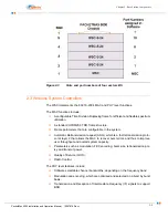
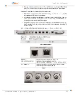
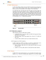
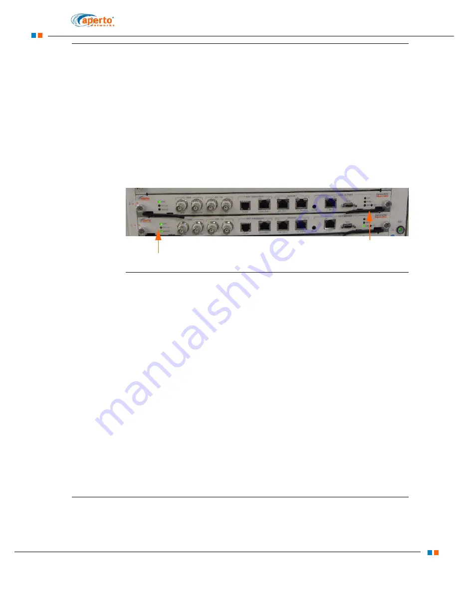
shows MSC Redundancy.
Figure 2-7
Redundant MSC
2.5.1 Redundancy support
MSC Redundancy support for PM 5000 is as follows:
A Redundant system should have QWC with WSC-48. Single slot WSC-24
Redundancy is not supported
The shelf manager version should greater than or Equal to 17 for MSC and
QWC cards.
The MSC, QWC and WSC should have the latest hardware revision.
EMS Configuration of MSC Redundancy
In EMS configuration of MSC redundancy, the actions as listed below can be
configured during switch over process using the Server Configuration tool.
1.
Reset: In this case, after switch over the active MSC will restart and connect
as standby MSC
2.
Shutdown: In this case, after switch over the active MSC will be shutdown.
2.6 AC Supply
The PM 5000 can accommodate either one or two (redundant) 1200 watt AC Power
Supplies.
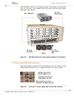
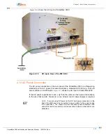
shows the redundant power supply [AC 2]. The AC Power Supply
Master
Ejector
Содержание PacketMAX 5000
Страница 10: ...Preface Preface vi PacketMax 5000 Installation and Operation Manual 10007678 Rev J ...
Страница 14: ...Table Of Content TOC 4 PacketMax 5000 Installation and Operation Manual 10007678 Rev J ...
Страница 38: ...1 20 PacketMax 5000 Installation and Operation Manual 10007678 Rev J Chapter 1 Overview Of Base Station ...
Страница 64: ...2 26 PacketMax 5000 Installation and Operation Manual 10007678 Rev J Chapter 2 Base Station Components ...
Страница 104: ...5 16 PacketMax 5000 Installation and Operation Manual 10007678 Rev J Chapter 5 Commissioning the Base Station ...
Страница 114: ...A 10 PacketMax 5000 Installation and Operation Manual 10007678 Rev J Chapter A Event Reporting ...
Страница 124: ...C 6 PacketMax 5000 Installation and Operation Manual 10007678 Rev J Chapter C Cables Spares and Accessories ...
Страница 146: ...E 4 PacketMax 5000 Installation and Operation Manual 10007678 Rev J Chapter E Certifications ...
Страница 150: ...F 4 PacketMax 5000 Installation and Operation Manual 10007678 Rev J Chapter F Troubleshooting ...


