


CHECK/ADJUST
NOZZLE
CO
‐
PLANARITY
WITH
BOARD
LEVEL
Turn
on
machine
and
open
software
The
following
procedure
is
for
making
sure
that
the
reflow
nozzle
edges
are
parallel
or
co
‐
planar
to
pcba
or
board
level
23. Attach
a
reflow
nozzle
to
the
APR
nozzle
ring.
The
preferred
nozzle
size
is
a
large
size,
NZA
‐
400
‐
400
or
NZA
‐
450
‐
450
for
example.
24. If
available,
install
an
unpopulated
pcba
into
the
board
holder.
If
necessary,
reverse
mount
the
bottom
plate
of
the
optical
kit
so
bottom
faces
up.
All
that
is
needed
is
a
flat
surface
at
pcba
level
to
compare
with
nozzle
edge.
25. Verify
that
the
board
is
level
in
board
holder
26. Remove
any
VNZ
pipette
from
the
vacuum
tube,
it
will
not
be
necessary
for
this
procedure.
27. Bring
the
head
downward
in
FAST
speed
until
head
stops.
Switch
to
COARSE
speed
and
bring
down
reflow
nozzle
edge
to
about
0.25”
(10.0mm)
above
board
level.
Switch
to
FINE
speed
and
adjust
to
5
‐
10
mil
or
as
needed.
Bring
the
head
down
until
the
reflow
nozzle
edges
are
just
above
board
level.
28. Examine
all
4
sides
of
the
reflow
nozzle
edges
with
respect
to
board
level.
All
4
sides
should
be
parallel
to
board
level.
29.
If
nozzle
edges
are
not
parallel
or
co
‐
planar,
adjust
the
3
spring
‐
loaded
screws
holding
the
heater
head
assembly
to
the
head
casting.
For
side
‐
to
‐
side
(pivot)
adjustment
concentrate
on
2
rear
screws.
For
front
‐
to
‐
rear
(pivot)
adjustment
concentrate
on
front
screw.
Final
adjustment
may
require
a
combination
of
the
3
adjust
screws.
NOTE:
Ensure
that
3
screws
for
holding
heater
head
assembly
are
not
too
loose
so
the
heater
head
is
hanging
loosely
off
the
head
casting.
If
screws
get
too
loose,
tighten
up
all
3
screws
to
get
a
new
starting
point
and
start
co
‐
planarity
adjustment
over.
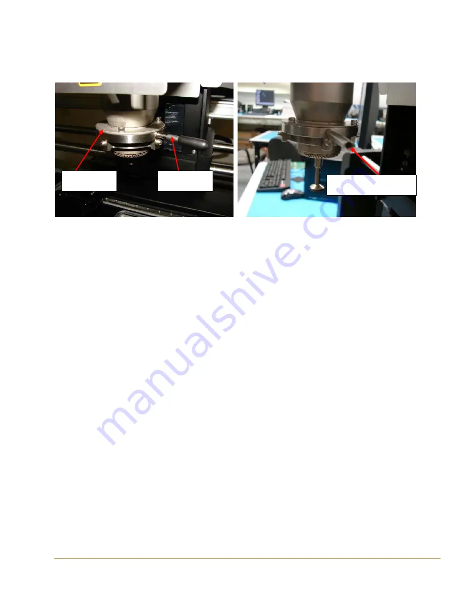
Nozzle lever
Nozzle ring
Adjust set screw inside to
tighten nozzle ring