


8
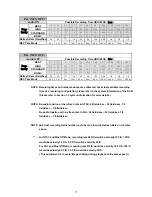
2.3
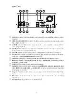
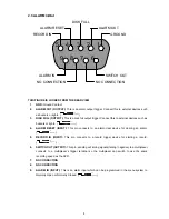
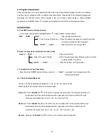
ALARM
In/Out
ALARM IN
ALARM OUT
RECORD IN
GROUND
DISK FULL
ALARM RESET
NO CONNECTION
NO CONNECTION
SWITCH OUT
1
2
3
4
5
6
7
8
9
THIS FIGURE IS LOOKED FROM THE REAR VIEW
1. GND:
Ground Contact.
2.
ALARM OUT (OUTPUT):
This is an alarm output trigger. Connect this to external devices such
as buzzers or lights. (
5V
0V(Active)
)
3.
DISK FULL (OUTPUT):
This is a disk full output trigger. Connect this to external devices such as
buzzers or lights. (
5V
0V(Active)
)
4. ALARM
RESET
(INPUT):
This pin connects to an alarm-clear device for clearing an alarm.
(
5V
0V(Active)
)
5.
RECORD IN (INPUT):
This pin connects to a record trigger device for starting a record.
(
5V
0V(Active)
)
6.
SWITCH OUT (OUTPUT):
This pin, sending out timing signals (falling / negative) to a multiplexer,
connects to a multiplexer’s trigger terminal so the multiplexer can switch to use the same
recording speed as the DVR.
7. NO
CONNECTION
8. NO
CONNECTION
9.
ALARM IN (INPUT):
This is an alarm input which can be programmed in the menu system to
Normally Open or Normally Closed. (
5V
0V(Active)
)
Содержание DVR-3011S
Страница 2: ......


