background image

- 4 - 

5. Informative list of spare parts of riveting tool: 

Position 

Article Nr. 

Name of part 

Pcs 


D-14001XX 

Mandrels 


S-14003XX 

Anvils complete 


D-1400400 

Joint sleeve 


D-1400500 

Counternut 


D-1401000 

Joint shaft 


S-1400600 

Front nozzle complete 


0901 

D-1400610 

Front nozzle body 


0902 

D-1400620 

Front nozzle with scale 


0903 

D-1400630 

Front nozzle pin 


0904 

D-1400640 

Adjusting nut 


0905 

D-1400650 

Washer 


0906 

N-1500000010005 

Compression spring 2x27x40x4,5  


0907 

D-1400670 

Covering sleeve 


0908 

D-1400680 

Retained ring 


0909 

D-1400690 

Spring 


0910 

N-3600000000005 

Steel ball dia. 4,5 

10 


N-2103702400150 

O – ring  24/1,5  Sh 70 

A23 


S-1407700 

Hydraulic body 

16 


D-1100800 

Hanger 

A24 


S-1400900 

Hydraulic piston complete 


20 

D-1406200 

Guiding band 

A25 


S-1407000 

Motor complete 


23 

D-1406600 

Pneumatic seal 35x28x4,5 


24 

S-1405000 

Motor  


27 

N-2103703000200 

O - ring  30/2  Sh 70 

25 


N-2103704200150 

O - ring  42/1,5  Sh 70 

26 


D-1404000 

Rear screwing 

28 


D-1404100 

Nut 

29 


N-3600000000003 

Steel ball 5 

31 


D-00220600 

Spring D10 

A35 


S-1404300 

Nut complete 


28 

D-1404100 

Nut 


30 

N-3704900208050 

Permanent magnet 20x8x5 


32 

D-1404200 

Sleeve 


33 

D-1404300 

Sleeve of permanent magnet 


34 

D-1404800 

Cover of permanent magnet 


35  

S-1404400 

Pin complete 


36  

D-08411500 

Spring 


37  

D-1404500 

Bush for pin 

38 


D-1404600 

Rear body 

39 


D-1404700 

Push button 

A36 


S-1407800 

Insert PP complete 


40 

N-2103901000200 

O - ring  10/2 Sh 90 


41 

S-1401800 

Insert PP 


42 

N-2104001800220 

O - ring  18/2,2 

A39 


S-1101900 

Valve piston complete 

A40 


S-1102000 

Valve body complete 

47 


N-2406696500090 

Plastic ball 9 

A41 


S-1102100 

Valve bottom 

50 


N-1000798408200 

Screw  M8x20 DIN 7984 

A47 


S-1402305 

Air supply ring complete 


52 

N-2103706000200 

O - ring   60/2  Sh 70 


53 

N-2103706300200 

O - ring  63/2  Sh 70 


54 

D-1102305 

Air supply ring 

67 


S-1103203 

Aircoupling 


A43 

S-1103213 

Aircoupling body complete 


A44 

S-1103221 

Aircoupling rotary part complete 


6705 

N-1402292500012 

Retaining ring 

55 


D-1102403 

Body bottom 

59 


D-1402700 

Pneumatic piston 

60 


N-2103900400150 

O - ring  4/1,5 Sh 90 

61 


N-1000091204080 

Screw M4x8  DIN 912 

A45 


S-1402801 

Pneumatic piston complete 


62 

D-1402801 

Pneumatic piston 


63 

N-2300007140000 

Pneumatic seal  14 


64 

D-1106400 

Pneumatic seal  70x60x4,5 

65 


D-1103001 

Pneumatic cylinder 

66  


D-1403100 

Tube 

68  


N-2103700700200 

O - ring   7/2  Sh 70 

69 


N-2103700400150 

O - ring   4/1,5  Sh 70 

A46 


S-1103300 

Trigger body complete 

73 


D-1103400 

Trigger piston 

74 


D-1103500 

Trigger 

76 


D-1103800 

Pin 

79 


D-1103600 

Nut of body 

80 


D-1103700 

Soft sleeve 

81 


N-1000091404050 

Screw M4x5 imbus DIN 914 


Содержание AirPower Series

Страница 1: ...Repair Manual AirPower4 Model Z 14026001 Hydraulic Threaded Insert Tool ...

Страница 2: ...ice set 11 List of special tools assembly jigs into the service set 1 Abbreviations CA compressed air MP special tool assembly jig D defect BEM basic engine monitoring 2 General instructions 1 Riveting tool is always deconnected from the compressed air unless otherwise stated 2 All threads are clockwise 3 Riveting tool is gripped in a stand see chapter 10 while assembling and disassembling unless ...

Страница 3: ...ng out stops Pos 39 gets back to the initial position motor turns off air does not leak Turn with stroke adjustement Further instructions are in the Operations manual The scale moves left stroke right stroke point of view from pos A23 pos 3 springs Put a rivet on pos 1 and press towards the riveting tool the rivet screws on Motor turns right outlet of CA through the outlets in pos 39 when the rive...

Страница 4: ... 3 4 Assembly drawing of riveting tool ...

Страница 5: ...4800 Cover of permanent magnet 1 35 S 1404400 Pin complete 1 36 D 08411500 Spring 1 37 D 1404500 Bush for pin 1 38 D 1404600 Rear body 1 39 D 1404700 Push button 1 A36 S 1407800 Insert PP complete 1 40 N 2103901000200 O ring 10 2 Sh 90 1 41 S 1401800 Insert PP 1 42 N 2104001800220 O ring 18 2 2 1 A39 S 1101900 Valve piston complete 1 A40 S 1102000 Valve body complete 1 47 N 2406696500090 Plastic b...

Страница 6: ...Screw on pos 65 with pos 80 put on MP14 tighten and put coloured warranty plug In case of using new parts pos 65 and pos 80 the process is different at first screw on pos 65 put MP14 on tighten and put coloured warranty plug Then apply glue PATTEX EXPRESS FIX PL600 on pos 65 put on pos 80 by circular motion and position it according to the picture ...

Страница 7: ... 6 Step 2 Disassembly Release pos A45 Assembly Put on pos A45 ...

Страница 8: ...SAN put pos 59 in pos A36 range about 68 mm screw on MP19 tightly to the stop position screw on MP13 filled with hydraulic oil to the pos 59 Then repeatedly press and release the piston MP13 until air bubbles stop leaking from the hydraulic system to MP13 MP13 must be always filled with hydraulic oil if not fill it After filling the hydraulic system of the riveting tool with hydraulic oil screw ou...

Страница 9: ... 79 divert pos 66 from MP11 because the surface of pos 66 might be damaged and screw out pos 79 Assembly Screw pos 79 on thread pos A36 put MP11 on locks pos 79 divert pos 66 from MP 11 because the surface of pos 66 might be damaged Retighten pos 79 ...

Страница 10: ...os 69 out with MP32 be careful and do not damage recess in pos 55 Put pos 55 out of pos A47 Assembly Put pos 55 on pos A47 insert pos 66 to pos 55 Lubricate recess in pos 55 and insert in pos 68 and pos 69 and check the proper placing of pos 68 and 69 Put pos A47 with pos 67 68 69 and pos 55 on pos A23 screw on pos 50 2x and tighten with imbus key nr 5 ...

Страница 11: ... small amount of CA pos A39 A40 and A41 blow out off the pos A23 it is necessary to catch them e g to the cloth Assembly Inser pos A39 into pos A40 and insert this complet into pos A23 Insert pos 47 into pos A40 put on pos A41 and press to the strop to pos A23 Do not lubricate pos 47 ...

Страница 12: ...sembly Loosen pos A36 with MP33 key screw out and put out from pos A23 Assembly Check the sealing of pos 40 see Step 22 Put pos A36 on pos A23 screw on and tighten with MP33 key Check the proper position of the sealing ...

Страница 13: ...h hand put out pos 39 and take out pos 31 Assembly Put pos 31 on pin pos 39 put pos 39 on pos 38 and screw on this complete Screw on pos 81 and slightly tighten with imbus key nr 2 Put coloured warranty plug on pos 38 and pos 81 Be careful about proper mounting of pos 31 to pos 39 ...

Страница 14: ...ssembly Take out pos 29 4x with the help of MP32 Screw out pos A35 with wrench 30 Assembly Put on pos A35 and tighten pos A35 with wrench 30 Lubricate outlets in pos A35 with vaseline and press pos 29 4x into outlets ...

Страница 15: ... 14 Step 10 Disassembly Screw out pos 26 with hook spanner 30 32 and put out pos 25 Assembly Put pos 25 on pos 26 and srew this comlete into pos A23 Then tighten pos 26 with hook spanner 30 32 ...

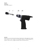
Страница 16: ...os A25 Assembly Put on pos A25 and move around a slight amount so that hexagon pos A25 and pos 8 match then move pos A25 to the stop Turn pos 1 to check if the installation was successful rotation in pos A25 must be obvious and audible ...

Страница 17: ...crew pos 1 on pos 6 to the stop and move back a slight amount so that hexagon pos 1 and pos 6 match Put pos 3 on pos 1 and pos 6 so that hexagon socket pos 3 match with hexagon pos 1 and pos 6 screw on to pos 9 Tighten the backnut in pos 3 to the front of pos 9 ...

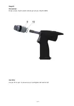
Страница 18: ... 17 Step 13 Disassembly Screw out pos 9 with wrench 24 and put out pos 10 with MP32 Assembly Put pos 10 on pos 9 screw on pos 9 and tighten with wrench 24 ...

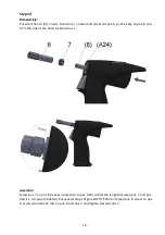
Страница 19: ... and from the side of the dart screw out pos 7 Assembly Screw pos 7 on pos 8 recess in direction to pos A24 so that the lenght between pos 7 and pos A24 is 1 mm see the detail Put several drops of glue LOCTITE 243 on thread pos 8 screw on pos 6 screw wrenches 12 2x on pos 6 and pos 7 and tighten towards pos 7 ...

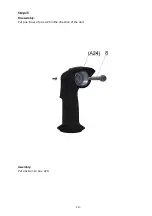
Страница 20: ... 19 Step 15 Disassembly Put pos 8 out of pos A24 in the direction of the dart Assembly Put pos 8 on to pos A24 ...

Страница 21: ...ternal surface of pos A24 inner surface of pos A23 and related sealing of pos A24 and pos 23 with silicon paste LUKOSAN secure pos 20 in the pos A24 with O ring 32 3 see the picture then insert pos A24 to the pos A23 to the stop pos A24 must slide in pos A23 O ring 32 3 will loosen while inserting pos A24 to pos A23 it is not a part of the riveting tool ...

Страница 22: ...re to the pos 76 and knock out with a hammer from pos A23 put out pos 74 Assembly Put on pos 74 put on pos 76 and beat in with hammer and a pin cca 2 8 mm in diametre so that the pos 76 is placed symmetrically in pos A23 Put coloured warranty plug on pos 76 ...

Страница 23: ...0 to the locks of pos A46 and screw out together with pos 73 take pos 73 out of pos A46 Assembly Screw pos A46 on pos 23 with the help of MP10 so that the front sides of both positions were neck and neck then insert pos 73 to pos A46 ...

Страница 24: ... 23 Step 19 Disassembly Take pos 16 out of pos A23 Assembly Put pos 16 on pos A23 ...

Страница 25: ...osen sub assemblies steps 20 25 Step 20 pos A45 Disassembly Put pos 64 out of pos 62 take pos 63 out of pos 62 with MP32 be careful and do not damage recess in pos 62 Assembly Insert pos 63 to pos 62 so that the pos 63 does not twist off Put pos 64 to pos 62 ...

Страница 26: ... of pos 41 with the help of MP32 while putting out be careful and do not damage recess in pos 41 Assembly Put pos 42 on pos 41 be careful while putting it on and do not damage pos 42 with a thread on pos 41 Lubricate the recess in pos 41 and put it on pos 40 ...

Страница 27: ...3 out of pos 24 with the help of MP32 while putting out be careful and do not damage recesses in pos 24 Assembly Put pos 27 on pos 24 Put pos 23 into the recess pos 24 Is necessary to keep the orientation pos 23 into the recess pos 24 according to detail ...

Страница 28: ...ul and do not damage recesses in pos 54 Disassembly pos 6705 put pos A44 out of pos 43 put a pole of 3 mm in diametre into the outlet in pos A43 and screw pos A43 out of pos 54 Assembly Screw pos A43 on pos 54 put pos A44 on pos A43 and secure pos 6705 Insert pos 52 and pos 53 to recesses pos 54 ...

Страница 29: ... 0910 and pos 0909 Assembly Put pos 0906 and pos 0905 on pos 0901 check the proper orientation pos 0905 see picture Carry on with one of following procedures procedure 1 when grooves in pos 0901 are open see picture put pos 0904 on pos 0902 and press pos 0903 2x into the holes of pos 0902 Put the complete set pos 0902 and pos 0903 with pos 0904 in pos 0901 lubricate all contact surfaces slightly w...

Страница 30: ...os 30 and pos 32 out of pos 33 Beware of bounce of pos 28 from spring pos 36 Assembly Put pos 32 and pos 30 into pos 33 Press pos 34 onto pos 33 Put out pos 37 pos 36 and pos 28 on pos 35 Put several drops of glue LOCTITE 243 on thread pos 35 put wrench MP18 into recess pos 37 put wrench MP17 into hexagon socket pos 32 and screw pos 35 into pos 32 Caution this operation require certain force to pu...

Страница 31: ...16 CA leaks through outlets in pos 39 9 Description of defects and their remedies Defect Operation Step Change of pos BEM turn pos 1 there must be rotation in pos A25 check if pos 1 slides freely cca 1mm NO disassembly pos 3 1 9 12 13 check deformation of hexagon pos 1 6 3 must slight freely 1 3 6 check tightening of pos 6 7 and clearance 1 mm 14 check cracking of pos 1 6 8 1 6 8 disassembly to po...

Страница 32: ...everything as in D11 D13 CA leaks in pos 67 Yes disassembly pos 67 23 67 NO disassembly pos 65 80 A45 79 50 55 A47 67 1 2 4 5 A47 NO disassembly pos A39 A40 A41 47 6 check sealing of pos A39 A40 A41 check surface of pos 47 and seating pos A41 A39 A40 A41 47 NO disassembly pos 59 A36 3 7 21 A36 42 D14 disassembly pos 65 80 A45 1 2 check inner surface pos 65 65 80 check sealing pos A45 20 A45 63 64 ...

Страница 33: ...4 NO outlet from pos A47 furter see D9 YES outlet from pos A47 further see D8 D8 disassembly pos 65 80 A45 61 60 1 2 3 fill in hydraulic oil 3 if necessary disassembly all check functional surfaces and sealing of pos A23 A24 A36 59 A23 A24 A36 59 D9 accomplish steps see D11 D12 D13 D14 D10 press and release pos 74 NO outlet from pos A47 further see CH9 YES outlet from pos A47 disassembly to pos 36...

Страница 34: ... 33 10 Service set Order Nr of service set is S 1002002 ...

Страница 35: ...4 MP11 S 1002110 1 Wrench MP11 SERIE 1 SERIE 2 SERIE 3 SERIE 4 MP12 S 1002120 1 Wrench MP12 SERIE 1 SERIE 2 SERIE 3 MP13 S 1002130 1 Oil filling tool MP13 SERIE 1 SERIE 2 SERIE 3 SERIE 4 MP14 N 5200900002140 1 Belt wrench 23 600 SERIE 1 SERIE 2 SERIE 3 SERIE 4 MP15A D 1002150 1 Sleeve MP15A SERIE 1 SERIE 2 SERIE 3 MP15B D 1002151 1 Sleeve MP15B SERIE 4 MP16B D 1002161 1 Threader MP16B SERIE 1 SERI...

Страница 36: ...Call our friendly knowledgeable factory trained service technicians today discover what makes us different 800 563 1293 www applifast com ...

Отзывы: