4
1-3 Front Panel
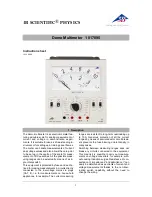
Refer to Figure 1 and to the following numbered steps to familiarize yourself with the meter’s front panel controls
and connectors.
1. Digital Display
— The digital display has a 4000 counts LCD readout with 82 segments analog bar graph, auto
polarity, decimal point, “
“ AC, DC
RANGE, APO and unit annunciators.
2. Rotary Switch
— Select the Function and Range desired.
3. COM Input Terminal
— Ground input connector.
4. V
Ω
Hz Input Terminal
— Positive input connector for Volts, Ohms Capacitance and Temperature Frequency.
5. mA Input Terminal
— Positive input connector for Amp measurements (up to 400mA).
6. A Input Terminal
— Positive input connector for Amp measurements (up to 10A).
7. Range Switch, (Manual Range)
— “Range” switch is pressed to select manual ranging and to change ranges.
When pressed the “Range” annunciator is displayed. Consecutively pres s-
ing the “Range” switch allows selection of the appropriate range for meas-
urement. To return to “Autoranging” press the “Range” switch and hold
simultaneously for 2 seconds.


