

APOLLO VISUAL OIL MONITOR INSTRUCTIONS
www.dunravensystems.com
Ver122014
The Apollo Visual product consists of:
1 x Apollo Ultrasonic Tank Transmitter
1 x Apollo indoor receiver plug
2 x Stainless steel fitting screws
1 x Weather seal
Step 4 - Fitting the transmitter (after matching)
The procedure is the same for fitting to both old and new tanks.
For Tank with pre-drilled
30/32mm hole
-
Remove the cap from the hole
and insert transmitter, ensuring
the weather seal is securely in
place.
- Ensure the transmitter is vertical
on top of the tank
-Tighten on to the tank using the 2 stainless steel 19mm long self
–
tapping screws supplied.
Do not use longer screws. Do not over
tighten.
For a Tank without a predrilled hole
-
If a tank is not predrilled, then using a 30/32mm hole saw, drill a
hole in the top of tank in suitable area to allow ease of fitting the
transmitter and in an area that the transmitter can see the tanks
contents. Position so that there are no internal obstructions.
(i.e. ribs, stays, side of tank, internal equipment) that might
interfere with the ultrasonic signal. Ensure the transmitter is a
minimum of 10cm from any tank wall or edge.
-
Use the Install Help diagram to insure suitable fitting.
-
Ensure the transmitter is vertical on top of the tank.
-
Tighten on to the tank using the 2 stainless steel 19mm long
self
– tapping screws supplied. Do not use longer screws. Do
not over tighten.
You have now completed the installation.
Always
set switch 1 up to
enable the low level audible
warning.
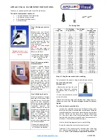
Step 1: Setting your receiver
plug
Measure your tank height,
from the base of the tank to
the
base
of
the
Apollo
transmitter location. Using the
Setting table provided on the
right, select the height closest
to your tank height.*NB. On a
bunded tank measure the
inner tank height*
Refer to the lower height
available.
E.g. if your tank height is
975mm choose the setting of
950mm on the table.
Set your pins to the required
setting. E.g. 1400 mm height
pins 1,3,5,6,8 in the up
position.
Step 2: Choosing a suitable
electrical socket
Choose a suitable electrical
socket, located in closest
proximity to the tank. The area
should be free of other
electrical appliances, wiring
and any large steel or metal
devices which could hinder the
FM signal between the tank
transmitter and receiver. Plug
your receiver plug into the
socket and switch on - the top
bar will flash to indicate the
unit is in learn mode and
ready for matching. This bar
will continue to flash for a
period of 2 Minutes.
Step 3: Matching the units
Note the black dot on the right
hand side of the receiver. Note
the black dot on the left hand
side of the tank transmitter.
Whilst the top bar is flashing
on the receiver hold the tank
transmitter
against
the
receiver as shown, so that the
black dots are aligned with the
display screens facing you, as
shown. Hold together. The
bars will increase up the
display screens. ONLY when
all 10 bars are shown, will they
flash to indicate that, the
unique code is transferred and
the units are matched.
Remove the transmitter from
the monitor immediately once
all 10 of bars are reached.
Tank
Height mm
Pin Settings
in up position
Tank Height
mm
Pin
Settings in up
position
500
1
1750
1,3,4,5,6,7
550
1,7
1800
1,2,8
600
1,6,8
1850
1,2,7,8
650
1,6,7,8
1900
1,2,6,7
700
1,5,7
1950
1,2,5
750
1,5,6
2000
1,2,5,7,8
800
1,5,6,7,8
2050
1,2,5,6,8
850
1,4,8
2100
1,2,4
900
1,4,6
2150
1,2,4,7
950
1,4,6,7
2200
1,2,4,6,8
1000
1,4,5,8
2250
1,2,4,6,7,8
1050
1,4,5,7,8
2300
1,2,4,5,7
1100
1,4,5,6,7
2350
1,2,4,5,6
1150
1,3
2400
1,2,4,5,6,7,8
1200
1,3,7,8
2450
1,2,3,8
1250
1,3,6,8
2500
1,2,3,6
1300
1,3,5
2550
1,2,3,6,7
1350
1,3,5,7
2600
1,2,3,5,8
1400
1,3,5,6,8
2650
1,2,3,5,7,8
1450
1,3,5,6,7,8
2700
1,2,3,5,6,7
1500
1,3,4,7
2750
1,2,3,4
1550
1,3,4,6
2800
1,2,3,4,7,8
1600
1,3,4,6,7,8
2850
1,2,3,4,6,8
1650
1,3,4,5,8
2900
1,2,3,4,5
1700
1,3,4,5,6
3000
1,2,3,4,5,6,8
Oil Level Monitor
Thank you for purchasing the Apollo Visual Oil Level Monitor
Pin Setting Table


