


APOGEE ELECTRONICS
6
Maestro
– User’s Guide
APOGEE ELECTRONICS
7
Maestro
– User’s Guide
Input Pane
Maestro Mixer Window
Input/Output Panes
The Input and Output Routing panes consist of an intuitive routing grid on which connections between hardware and
software I/O are depicted and modified visually.
Connections are depicted by grey connection icons
at the intersection of a hardware I/O column and a soft-
ware I/O row. To modify a connection, place the curser over the grid at the intersection of the desired hardware I/O
column and software I/O row, and click on the highlighted grid position; the grey connection icon will shift into the new
position to indicate that the desired connection has been made.
As an example, the default state of the Input routing pane with an Ensemble connected is shown in figure 1 . Ensem-
ble’s hardware inputs are displayed across the top of the grid, while software inputs are displayed to the left of the
grid. The grey connection icons, labelled L and R, are placed such that hardware inputs
Analog In 1
and
2
are con-
nected to software
Input Analog 1/2
, hardware inputs
Analog In 3
and
4
are connected to software
Input Analog
3/4
, and so on.
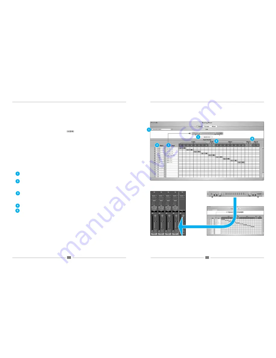
Input Pane
The Input pane serves to connect hardware inputs to software inputs, as shown in figure 2 . The following controls are
found in the Input pane:
1. Interface menu , Identify Unit
– These controls, found at the top of the Input, Output and Mixer panes, are identical
to those found in the Maestro Control window described on page 2.
2. Matrix
– The settings in these drop down menus define how software inputs are formatted in the routing grid:
Mono
- software inputs are formatted as Mono signal paths.
Stereo
- software inputs are formatted as Stereo signal paths.
Off
- the signal path is deactivated.
3. Input
– This column displays the software inputs available for routing. Software input names may be modified by
clicking on the triangle to the left of the Matrix to reveal a text entry box. For these names to appear in your audio
application’s I/O list, it’s necessary to specify this in the audio app. For example in Logic Pro, open
Audio>Audio
Configuration>View>I/O Labels
and Option-click on all the I/O found under the
Driver’s I/O Label
column
4. (Analog, Hardware) In
– This row displays the hardware inputs available for routing.
5. Mixer A In, Mixer B In
– It’s possible to route the output of either the A or B mixer (found in the Mixer pane) back into
the software application. For example, when hardware synths are connected to the hardware inputs of an Apogee
interface, it’s possible to mix these synths using the Maestro mixer and record the mix in your software application by
assigning either the
Mixer A In
or
Mixer B In
to a software path.
figure 2
figure 1


