


APC-3X14B User Manual
26
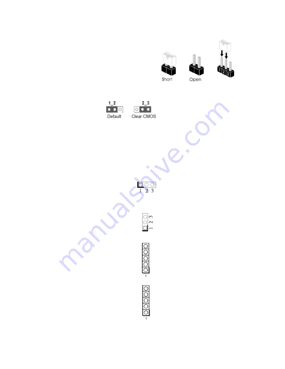
2.5 Jumpers Setup
The illustration shows how jumpers are setup.
When the jumper cap is placed on pins, the
jumper is “Short”. If no jumper cap is placed on
pins, the jumper is “Open”. The illustration shows
a 3-pin jumper whose pin1 and pin2 are “Short”
when jumper cap is placed on these 2 pins.
____________________________________________________________________________
Clear CMOS Jumper
(CLRCMOS1)
(see p.8, No. 16)
Note: CLRCMOS1 allows you to clear the data in CMOS. To clear and reset the system
parameters to default setup, please turn off the computer and unplug the power cord from
the power supply. After waiting for 15 seconds, use a jumper cap to short pin2 and pin3 on
CLRCMOS1 for 5 seconds. However, please do not clear the CMOS right after you update the
BIOS. If you need to clear the CMOS when you just finish updating the BIOS, you must boot
up the system first, and then shut it down before you do the clear-CMOS action. Please be
noted that the password, date, time, user default profile and MAC address will be cleared
only if the CMOS battery is removed.
____________________________________________________________________________
Digital Input / Output Power Select 1-2: +12V
(3-pin JGPIO_PWR1)
2-3: +5V
(see P.8, No. 17)
____________________________________________________________________________
ATX/AT Mode Selection 1-2: AT Mode
(3-pin PWR_JP1)
2-3: ATX Mode
(see p.8, No. 26)
____________________________________________________________________________
Panel Power Selection (LCD_VCC)
(5-pin PNL_PWR1)
(see p.8, No. 4)
____________________________________________________________________________
Backlight Power Selection
(LCD_BLT_VCC)
(5-pin BKT_PWR1)
(see p.8, No. 5)
Use this to set up the VDD
power of the LVDS connector.
1-2: LVDD: +3V
2-3: LVDD: +5V
4-5: LVDD: +12V
Use this to setup the backlight
power of the LVDS connector
and the panel backlight power
of BLT_PWM1.
1-2: LCD_BLT_VCC: +5V
2-3: LCD_BLT_VCC: +12V
4-5: LCD_BLT_VCC: DC_IN
Содержание APC-3514B
Страница 2: ...APC 3X14B User Manual 1 Revision History Reversion Date Description 1 0 2015 09 02 Official Version ...
Страница 9: ...APC 3X14B User Manual 8 1 3 Dimentions Figure 1 1 Dimensions of APC 3514B ...
Страница 10: ...APC 3X14B User Manual 9 Figure 1 2 Dimensions of APC 3714B ...
Страница 11: ...APC 3X14B User Manual 10 Figure 1 3 Dimensions of APC 3914B ...
Страница 13: ...APC 3X14B User Manual 12 Figure 1 6 Front View of APC 3714B Figure 1 7 Rear View of APC 3714B ...
Страница 14: ...APC 3X14B User Manual 13 Figure 1 8 Front View of APC 3914B Figure 1 9 Rear View of APC 3914B ...
Страница 21: ...APC 3X14B User Manual 20 2 2 Motherboard Layout Figure 2 1 Motherboard Layout ...
Страница 54: ...APC 3X14B User Manual 53 Step 3 Click Yes Step 4 Click Next to continue ...
Страница 55: ...APC 3X14B User Manual 54 Step 5 Read the License Agreement then click Yes Step 6 Click Next to continue ...
Страница 62: ...APC 3X14B User Manual 61 Step 4 Click Next to continue Step 5 Click Next to continue ...
Страница 64: ...APC 3X14B User Manual 63 Step 2 Click Next to continue Step 3 Click install to begin the installation ...
Страница 72: ...APC 3X14B User Manual 71 Step 6 Click Continue Anyway Step 7 Click Finish to complete installation ...


