background image


The above specifications were current at the time this manual was published, but because of 
our policy of continuous improvement, APEX Machine Group, reserves the right to change 
specifications at any time without prior notice. 


UNPACKING 

 
Open shipping container and check for shipping damage. Report any damage immediately to 
your distributor and shipping agent. Do not discard any shipping material until the collector is 
installed and running properly. Compare the contents of your container with the following parts 
list to make sure all parts are intact. Missing parts, if any, should be reported to your distributor. 
Read this instruction manual thoroughly for assembly, maintenance and other instructions. 
Be sure to check inside the filter, by opening the door to find manual and sample of additive for 
water. 
 

INSTALLATION AND ASSEMBLY OF UNIT 
 

ELECTRICAL INSTALLATION: 
 

All electrical work must be done by a qualified electrician or qualified person according to local, 
state and national codes.  
 

Caution: 

Installation can cause exposure to live components. Be sure to disconnect electrical 

power before proceeding with installation.  
 
Determine the location where the collector will be installed. Be sure to allow sufficient room  
around the unit to service the sludge collection bin, or roll the unit out of position. Allow for the  
inlet ducting and the exhaust air also. When selecting a location consider the floor surface;  
a smooth and level floor will be helpful when moving unit for cleaning. 
 

1.  Uncrate collector using caution not to damage the paint while lifting or dismantling the 

crate.  

2.  Remove any other item that may be on the skid.  
3.  When using a forklift, be careful lifting the unit as it is top heavy. 
4.  After placing the unit onto its location be sure to lock the front caster so the unit does not 

move.  

5.  When make the electrical connection, a quick power plug is recommended so it is easy to 

disconnect when unit is required to be moved for cleaning.  

6.  Check blower for proper rotation direction; if blower rotation is backward, interchange two 

of the motor lead connections. (L1 and L2) 

7.  Start unit by depressing the start button located on the starter box. 
8.  Check total current draw on the motor with water in the unit and at the proper level. If the 

amperage is higher than the rating on the motor, either the water level or the inlet needs 
to be blocked off to reduce the total amperage. (For best performance, the motor should 
run a few amps lower than total listed on motor name plate).  

9.  Water is added as needed through the front-loading door. Water should be filled to a level 

about ½ way up the water sight window. (Middle of sight glass or approx. 9” up). Note 

Содержание PWDC-5

Страница 1: ...1 Operations Manual Model PWDC 5 Wet Collector ...

Страница 2: ...he warranty does not cover those consumable items such as coolant or rust additives HOW TO GET SERVICE Contact APEX Machine Group at 855 500 2739 952 895 518 www apexmachinegroup com or the dealer you purchased the machine from Manufacture or Distributor is not responsible for and will not pay for work done material furnished or repairs made by others unless agreed to in writing prior to performin...

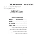
Страница 3: ... Minnesota 55422 Warranty Registration Card Model No ______PWDC 5 Collector________ Serial No ______________________________ Date Purchased ________________________ Company Name _________________________ Address _______________________________ ____________________________________ Phone No ______________________________ E mail Address __________________________ ...

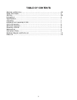
Страница 4: ...f Contents 4 Warning 5 6 Introduction 6 Specifications 7 Unpacking 7 Installation and Assembly of Unit 7 230 Volt Operation 8 460 Volt Conversion 8 Operating Controls 9 Maintenance 8 Connection Points 9 Electrical Diagram and Parts List 10 Parts List 16 ...

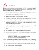
Страница 5: ... Group disclaims any real or implied warranty and holds itself unaccountable from any injury that may result from that use 6 Always wear approved safety glasses face shields while around collector Everyday eyeglasses only have impact resistant lenses they are not safety glasses 7 Before operating this collector or while cleaning it be sure to wear proper gloves and clothing 8 Wear ear protectors p...

Страница 6: ... procedures for this collector This manual contains instructions on installation safety precautions general operating procedures maintenance instructions and parts breakdown This collector has been designed and constructed to provide years of trouble free operation if used in accordance with instructions set forth in this manual If there are any questions or comments please contact either your loc...

Страница 7: ... the unit to service the sludge collection bin or roll the unit out of position Allow for the inlet ducting and the exhaust air also When selecting a location consider the floor surface a smooth and level floor will be helpful when moving unit for cleaning 1 Uncrate collector using caution not to damage the paint while lifting or dismantling the crate 2 Remove any other item that may be on the ski...

Страница 8: ...ress the green button labeled START Press the red button labeled STOP GENERAL MAINTENANCE 1 No lubrication of the main motor is required as it is permanent pre lube type Keeping it clean is all that is required 2 The sludge or sump should be raked or drained and washed out once the material reaches a certain level and effects the air flow 3 When cleaning the tank or sump tank area with this unit o...

Страница 9: ...9 ...

Страница 10: ...10 ...

Страница 11: ...11 ...

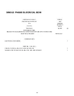
Страница 12: ...019 03 19 Sheng Description Symbol q ty REFERENCE ITEMS SEE ELECTRICAL NAMEPLATE FOR OPTIONS SUPPLIED WITH THIS MACHINE ELECTRICAL DIAGRAM 52303 00 E1 COMMON PARTS ELECTRICAL ENCLOSURE 1 HEAD NO 1 FLA 24 4 FUKUTA 5 HP 3450 IP54 FR 112M BI BY 230 1 60 1 NHD MS1 25D 1PH 5HP 230V 24 28A IP54 MS1 25D1H7N282P 1 ...

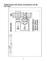
Страница 13: ...13 THREE PHASE ELECTRICAL DIAGRAM 230 OR 460 VOLTAGE ...

Страница 14: ...0 12 4 FLA 2012 06 19 Sheng Description Symbol q ty REFERENCE ITEMS SEE ELECTRICAL NAMEPLATE FOR OPTIONS SUPPLIED WITH THIS MACHINE ELECTRICAL DIAGRAM 52303 1 E1 E2 COMMON PARTS ELECTRICAL ENCLOSURE 1 HEAD NO 1 FLA 12 4 FUKUTA 5 HP 3450 IP54 FR 112M B3 MNT F2 BOX 230 460 3 60 1 NHD MS1 12D 3PH IP54 1 ...

Страница 15: ...012 06 19 Sheng Description Symbol q ty REFERENCE ITEMS SEE ELECTRICAL NAMEPLATE FOR OPTIONS SUPPLIED WITH THIS MACHINE ELECTRICAL DIAGRAM 52303 00 E2 COMMON PARTS ELECTRICAL ENCLOSURE 1 HEAD NO 1 FLA 6 2 FUKUTA 5 HP 3450 IP54 FR 112M B3 MNT F2 BOX 460 3 60 1 NHD MS1 12D 3PH 5HP 460V 7 5A IP54 MS1 12D 3S7N82P 1 ...

Страница 16: ...16 ...

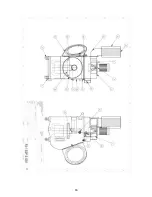
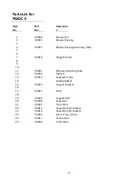
Страница 17: ...ht Caster 8 9 10 11 P 0001 Diffusor Mounting Tube 12 P 0002 Silencer 13 P 0012 Separator Tube 14 Sealing Gasket 15 P 0024 Support Bracket 16 17 P 0027 Knob 18 19 P 0026 Support Rod 20 P 0008 Separator 21 P 0003 Front door 22 P 0014 Separator Sprt Bracket 23 P 0015 Separator Sprt Bracket 24 P 0004 Silencer top screen 25 P 0017 Control Box 26 P 0006 Unit Frame ...

Страница 18: ...18 ...

Страница 19: ...19 ...

Страница 20: ...20 ...

Страница 21: ...21 ...

Страница 22: ...22 ...

Отзывы: