Setup
Document No. D106-009
Page 32 of 76
Revision 1.15
3.5.1.2.
M
ICRO
L
OGIX
/SLC
C
ONTROLLER
T
YPE
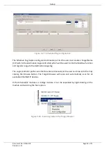
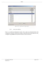
The MicroLogix/SLC controller paths can either be entered manually or the user can browse
to them by clicking the Browse button. The Target Browser will open and automatically scan
for all available EtherNet/IP devices.
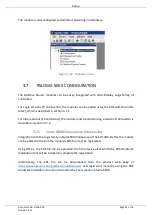
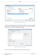
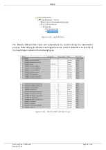
Figure 3.24 - Target Browser selection
The required MicroLogix/SLC controller can then be chosen by selecting it and clicking the Ok
button, or by double-clicking on the controller module. A maximum number of 3 controller
mapping entries can be added.
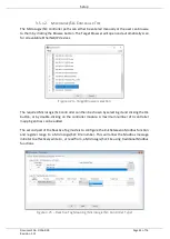
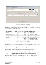
The second part of the Reactive Tag mode is to configure the link between a Modbus function
and register range to a MicroLogix/SLC File number. This will allow the Modbus message
initiator to effectively write to, or read from, a MicroLogix/SLC File using traditional Modbus
functions.
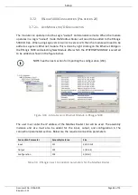
Figure 3.25 – Reactive Tag Mapping (MicroLogix/SLC Controller Type)


