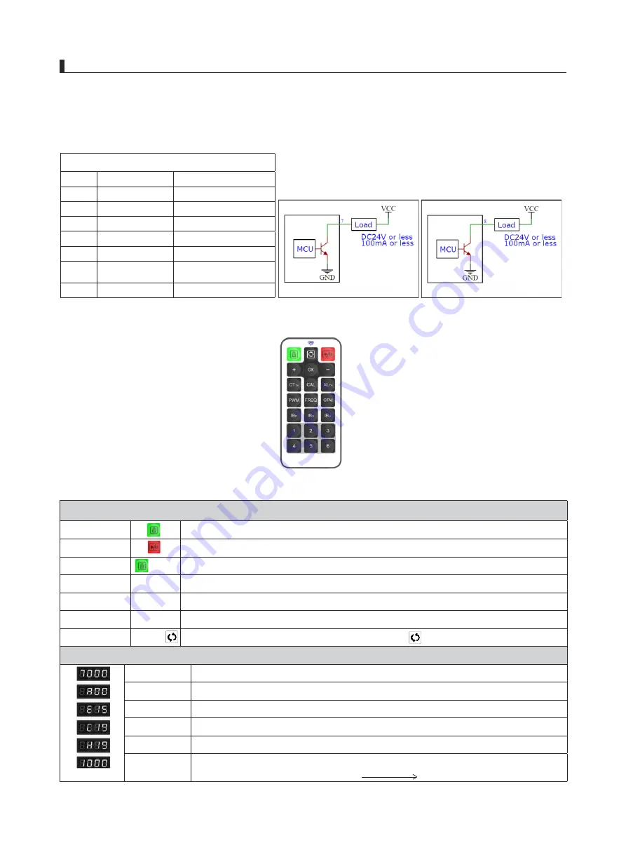
Network port cable function information
1
、
2
+24VDC
3
RS485+B
4
RS485+A
5
GND
6
GND
7
8
9
Metal shield
PE
The output wiring diagrams of pins 7 and 8 are as follows:
Button function instructions
Unlock, press +/- to switch the display of working address, cleaning cycle, working
environment temperature/humidity, alarm threshold
&7
7+
ĺ
$/
7+
ĺ
&$/ĺ 2.
'LVSOD\LQIRUPDWLRQGHVFULSWLRQ
7000
Display the real-time high-voltage output value of the high-voltage power supply
:
7000VAC
A00
Display the working address of the high-voltage power supply
:
00
E15
Display the cleaning cycle of the matching ion bar
:
15
(
Unit
:
day
)
C19
Display the internal working environment temperature of the high-voltage power supply
:
19
℃
H19
Display the internal working environment humidity of the high-voltage power supply
:
19%RH
1000
Display the alarm threshold of the high-voltage power supply: 1000VAC
&$/ĺ
ĺ
Installation Guide
1. Insert the national standard power cord plug into the mains socket.
2. Insert the high-voltage connector of the static elimination device into the high-voltage output socket of the power supply and connect its ground
terminal to the ground stud of the high-voltage power supply.
3. The switch indicator and status indicator light on(Green light on when working normally) and the display showing the working voltage value
normally indicates the power supply working normally when turn on the power switch.
4. One end of the communication network cable should be inserted into the RJ45 communication socket on the front panel of the power supply,
and the other end should be connected to a monitoring terminal or connected to a PC through a USB-485 converter If communication is
required. The port wiring and panel descriptions are as follows:
Orange/White-orange
Blue
White-blue
Green
White-green
Brown
White-brown
HV
AL
:
High voltage alarm
ACT
:
Power on indication
Clean
:
Cleaning indication
5
、
The cleaning cycle of the high-voltage power supply can be set by the remote control, as shown in the table below:
Unlock
Run / Pause
Parameter display
Adjust cleaning cycle
Adjust alarm threshold
Confirm
Reset
Unlock before adjusting operating parameters
Device starts running when power is on. Press "STOP" to standby and no high voltage
output. Press "RUN" again and the device will start working.
Press CT
TH
first, then press +/- to increase or decrease the cleaning cycle (Default 30
days, adjustment range is 1-60 days)
Press AL
TH
first, then press +/- to increase or decrease the high voltage alarm threshold
(Default 1000V, adjustment range is 500-2000V)
Press CAL first, then press OK to confirm after adjusting the output parameter
5HVHW
,
3UHVV&$/ILUVW
,
WKHQSUHVV
(eg
:
High voltage from 7000VAC 1000VAttenuation 6000VAC alarm)
HV Alarm signal:Normal--always
open
、
Abnormal--always close
Power signal :Normal--always close
cleaning signal
:Clean--always open


