AOpen DXPL Plus-U Скачать руководство пользователя страница 6


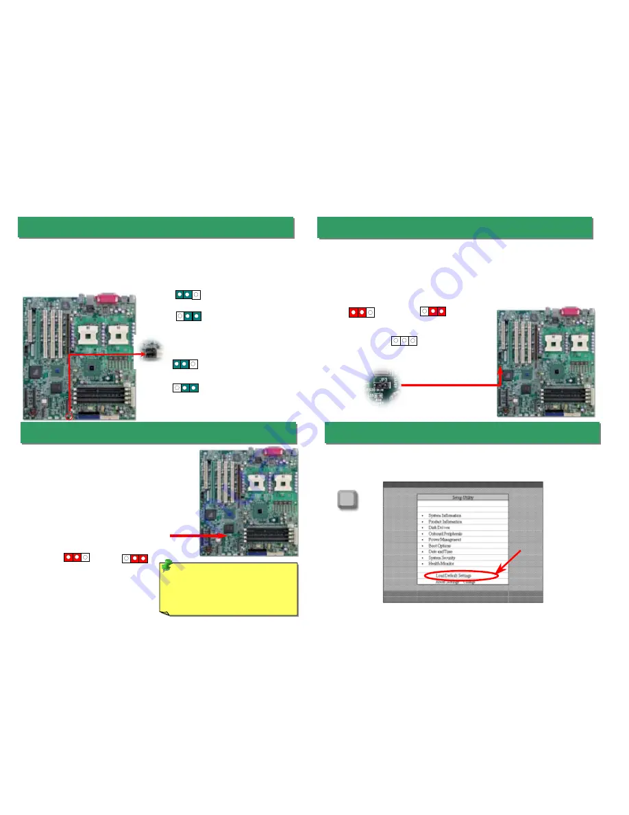
17.JP3 BIOS Configuration / Recovery Select Jumper


After you finish the setting of jumpers and connect correct cables. Power on and enter the
BIOS Setup, press <Del> during POST (Power On Self Test). Choose "Load Default
Setting" for recommended optimal performance.

16. JP2 Clear CMOS Jumper


15. JP1 Check Password / JP5 SCSI On/Off Jumper

Del 

You can clear CMOS to restore system default setting. To 
clear the CMOS, follow the procedure below. 

1. Turn off the system and unplug the AC power. 

2. Remove ATX power cable from connector PWR2. 

3. Locate JP2 and short pins 2-3 for a few seconds. 

4. Return JP2 to its normal setting by shorting pin 1 & pin 2.

5. Connect ATX power cable back to connector PWR2. 

Tip:

 When should I Clear CMOS? 

1. Boot fails because of overclocking…

2. Forget password… 

3. Troubleshooting…


Clear CMOS 

1

18. Power-On and Load BIOS Setup 

Normal Operation 

(default) 

This motherboard provides check password function. You can use JP1 to enable or disable
this function, which could prevent your system from unauthorized invasion. The factory
default setting is set to “Enable” (1-2), and you may disable this function by setting the
jumper to 2-3. Moreover, JP5 jumper is used to disable or enable SCSI function. The
factory default setting is set to “Enable” (1-2), and you may disable this function by setting
the jumper to 2-3. 

JP1 Password On (Default) 

JP5 SCSI On (Default) 

You can use JP3 to configure or recover your BIOS. The factory default setting is set to
“Normal” (1-2), and you may configure your BIOS by setting the jumper to 2-3, and recover 
your BIOS by removing the jumper.   

Configure

1

Normal (default) 

JP1 Password OFF 

JP5 SCSI OFF 

Recovery

1

Содержание DXPL Plus-U

Страница 1: ...IPMB connector JP5 SCSI ON OFF Select Jumper 64bit 100MHz PCI X Slot x1 with ZCR Function Support DXPL Plus U Intel 82545 EM GbE Ethernet Controller USB2 0 Connector JP2 Clear CMOS Jumper South Bridge...

Страница 2: ...DE Cable Package Plate plastic for retention module assembly x2 Plug in the CPU fan cable to the 3 pin CPU FAN connector and housing fan cable to the Chassis Fan connectors 1 Pull up the CPU socket le...

Страница 3: ...X connector before connecting the 24 pin ATX power connector 6 Connecting IDE and Floppy Cables The DXPL Plus U provides two 68 pin Ultra320 SCSI connectors for 16 bit or 16 bit differential SCSI devi...

Страница 4: ...terface specification defines a message based interface to platform monitoring and control function IPMI s monitoring abilities enable user to monitor server physical health characteristics such as te...

Страница 5: ...the signal sources such as CD Tape player Support 5 1 Channel MIC In From Microphone Support 5 1 Channel COM 2 Port COM 1 Port PS 2 Keyboard Connector USB2 0 Port MIC IN CENTER LFE Line IN SURROUND S...

Страница 6: ...fails because of overclocking 2 Forget password 3 Troubleshooting Clear CMOS 1 18 Power On and Load BIOS Setup Normal Operation default 1 This motherboard provides check password function You can use...

Страница 7: ...eyboard The problem was probably caused by power supply or motherboard failure Please contact your reseller or local distributor for repairing Perhaps your VGA card or monitor is defective No Yes No Y...

Страница 8: ...u 6 6 Contact Us Please prepare detail system configuration and error symptom before contacting us The part number serial number and BIOS version are also very helpful 7 7 Dear Customer Thanks for cho...

Отзывы: