


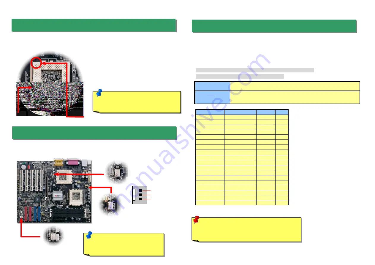
Plug in the CPU fan cable to the 3-pin
CPU FAN
connector. If you have housing fan, you
can also plug it on
System FAN
connector and
AUX FAN
.
CPU
CPU Core Frequency
FSB Clock
Ratio
Celeron 533
533MHz
66MHz
8x
Celeron 566
566MHz
66MHz
8.5x
Celeron 600
600MHz
66MHz
9x
Pentium III 600E
600MHz
100MHz
6x
Pentium III 650E
650MHz
100MHz
6.5x
Pentium III 700E
700MHz
100MHz
7x
Pentium III 750E
750MHz
100MHz
7.5
Pentium III 800E
800MHz
100MHz
8x
Pentium III 850E
850MHz
100MHz
8.5x
Pentium III 533EB
533MHz
133MHz
4x
Pentium III 600EB
600MHz
133MHz
4.5x
Pentium III 667EB
667MHz
133MHz
5x
Pentium III 733EB
733MHz
133MHz
5.5
Pentium III 800EB
800MHz
133MHz
6x
Pentium III 866EB
866MHz
133MHz
6.5
Pentium III 933EB
933MHz
133MHz
7x
Pentium III 1G
1GHz
133MHz
7.5x
Pentium III 1.13G
1.13GHz
133MHz
8.5x
Setting CPU Core Voltage
This motherboard supports CPU VID function. The CPU core voltage will be automatically
detected and the range is from 1.05V to 1.825V. It is not necessary to set CPU Core Voltage
Setting CPU Frequency
This motherboard is CPU jumper-less design, you can set CPU frequency through the BIOS
setup, no jumpers or switches are needed.
BIOS Setup > Frequency / Voltage Control > CPU Speed Setup
Core Frequency = CPU FSB Clock * CPU Ratio
CPU Ratio
3x, 3.5x, 4x, 4.5x, 5x, 5.5x, 6x, 6.5x, 7x, 7.5x, 8x, 8.5x, 9x, 9.5x, 10x, 10.5x, 11x, 11.5x,
12x, 12.5x, 13x, 13.5x, 14x, 14.5x, 15x, 15.5x and 16x
CPU
FSB
(By BIOS Table)
66.6, 79, 83.3, 85, 87.5, 90, 92.5, 95, 100, 110, 120, 124, 129, 133.3, 138, 143, 147, 152,
154, 157, 159, 162, 166, 171, 180, 190, and 200 MHz
5. Setting CPU Voltage & Frequency
4. Installing CPU & Housing Fan
3. Installing Processor
Warning:
VIA Apollo Pro 133T chipset supports
maximum 133MHz FSB and 66MHz AGP clock, higher
clock setting may cause serious system damage.
1.
Pull up the CPU socket lever and up to
90-degree angle.
2.
Locate Pin 1 in the socket and look for a
(golden) cut edge on the CPU upper interface.
Match Pin 1 and cut edge. Then insert the
CPU into the socket.
3.
Press down the CPU socket lever and finish
CPU installation.
Note:
If you do not match the CPU socket
Pin 1 and CPU cut edge well, it may
damage the CPU.
CPU Pin1 and
cut edge
CPU socket
Lever
Note:
Some CPU fans do not have
sensor pin, so that cannot support fan
monitoring.
CPU FAN2
Connector
FAN3
Connector
GND
+12V
SENSOR
CPU FAN
Connector
This socket supports FC-PGA/FCPGA2 package CPU, which is the latest CPU package
developed by Intel, we strongly recommend you not to insert former PPGA-package CPU
onto it.


