AOpen DX2G Plus Скачать руководство пользователя страница 7

AOpen DX2G Plus System Board

1-7

1.4.2

Jumper Settings

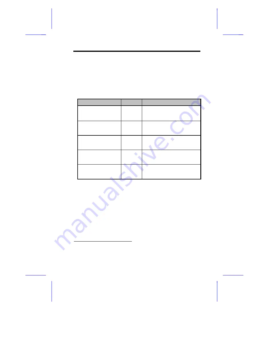
Table  1-1  lists  the  system  board  jumpers  with  their  corresponding
settings and functions.

Table 1-1

System Board Jumper Settings

Jumper

Setting

Function

BIOS Logo

JP3

1-2*
2-3

Logo
OEM

Password Security

JP4

1-2
2-3*

Check password
Bypass password

Boot Block Mode

JP5

1-2*
2-3

Disabled
Enabled

Sound Output

JP6

1-2*
2-3

Buzzer
Speaker

AlertPack Select

JP7

1-2/4-5
2-3/5-6*

AlertPack and LM80
LM80 Only


*   Default

Содержание DX2G Plus

Страница 1: ...ntium II III Xeon processor implements a Dynamic Execution micro architecture a unique combination of multiple branch prediction data flow analysis and speculative execution This means that the Pentiu...

Страница 2: ...in traditional workstations AOpen DX2G Plus has a built in dual channel Ultra2 SCSI Small Computer System Interface system This system enables the throughput of a single channel SCSI bus to reach 80MB...

Страница 3: ...Energy Star program It also offers the Plug and Play feature This feature saves the user from configuration troubles thus making the system more user friendly For the default configuration DX2G Plus...

Страница 4: ...m clock calendar with battery backup One 50 pin fast SCSI and two 68 pin Ultra2 SCSI interfaces I O APIC device for SMP interrupt support Integrates an enhanced PCI local bus IDE controller Intel 440G...

Страница 5: ...ature Connector supports Intel SMM cards 18 System BIOS 19 RDM connectors 20 Channel 2 fast narrow SCSI connector 50 pin 21 Channel 1 Ultra wide Ultra 2 SCSI connector 68 pin 22 Channel 2 Ultra wide U...

Страница 6: ...nd Connector Locations Figure 1 2 shows the jumper and connector locations on the system board Figure 1 2 System Board Jumper and Connector Locations Jumpers are prefixed P Connectors are prefixed N T...

Страница 7: ...and functions Table 1 1 System Board Jumper Settings Jumper Setting Function BIOS Logo JP3 1 2 2 3 Logo OEM Password Security JP4 1 2 2 3 Check password Bypass password Boot Block Mode JP5 1 2 2 3 Di...

Страница 8: ...ng in Connector CN10 Parallel above Serial 1 left and Serial 2 right Ports CN11 USB Connectors CN12 CPU1 Fan Connector CN13 CPU2 Fan Connector CN14 RJ 45 LAN Port CN15 Fail Report LED Connector CN16 C...

Страница 9: ...X2G Plus CN35 External Speaker Connector CN36 Hard Disk LED Connector CN37 Hard Disk LED Connector CN38 Power Switch Connector CN39 47 RDM ASM Module Connector not used by AOpen DX2G Plus CN40 Wake on...

Страница 10: ...nt 1 Do not remove a component from its antistatic packaging until you are ready to install it 2 Wear a wrist grounding strap before handling electronic components Wrist grounding straps are available...

Страница 11: ...d possible higher frequencies whereas a Slot 1 processor accesses the L2 at only half the CPU clock speed This significantly boosts performance and speed 1 6 1 Installing the Retention Mechanisms Foll...

Страница 12: ...Slot 2 retention holes and secure the retention mechanisms with eight screws six screws see figure below to secure the retention mechanisms and two screws afterwards when fitting the system board to...

Страница 13: ...Installing an Intel Pentium II III Xeon processor Follow these steps to install a Pentium II III Xeon processor 1 Attach the fansink module to the Pentium II III Xeon processor and secure it with four...

Страница 14: ...rt the Pentium II III Xeon processor into an empty Slot 2 socket Figure 1 6 Installing a Pentium II III Xeon Processor 3 Carefully press down the Pentium II III Xeon processor until it is properly ins...

Страница 15: ...mechanism cover only fits one way Both shafts of the retention mechanism and the retention mechanism cover have a O and a OO sign Match the O on the cover with the O on the retention mechanism first...

Страница 16: ...moving a Retention Mechanism Cover 2 Flip up both plastic ears of the Pentium II III Xeon processor This procedure detaches the processor from the socket Figure 1 9 Removing a Pentium II III Xeon Proc...

Страница 17: ...a terminator board 1 Position the terminator board over the empty slot 2 Carefully insert the golden fingers of the terminator board into the slot until the board fits completely Figure 1 10 Installin...

Страница 18: ...on mechanism first then hook them together and insert the OO side onto the retention mechanism make sure both sides are securely clipped To remove the terminator board 1 Unclip the retention mechanism...

Страница 19: ...ealer for qualified DIMM vendors Do not use both 100 MHz registered and 66 MHz standard unbuffered SDRAM together Such a combination might cause your system to malfunction Each of the DIMM sockets is...

Страница 20: ...MB 256 MB 256 MB 768 MB 256 MB 256 MB 256 MB 256 MB 1024 MB 512 MB 512 MB 512 MB 512 MB 1024 MB 512 MB 512 MB 512 MB 1536 MB 512 MB 512 MB 512 MB 512 MB 2048 MB 1 7 2 Installing a DIMM To install a DI...

Страница 21: ...3 Removing a DIMM To remove a DIMM press the holding clips on both sides of the socket outward to release the DIMM Place your forefingers on the top of the DIMM before you press the holding clips to g...

Страница 22: ...removing DIMMs Follow these steps to reconfigure the system 1 Reboot the system A memory error message appears indicating that the total memory does not match the value stored in CMOS 2 Press 3 Press...

Страница 23: ...slot Make sure that the card is properly seated 4 Secure the card to the housing with a screw When you turn on the system BIOS automatically detects and assigns resources to the PCI devices Figure 1...

Страница 24: ...IOS will not use the resources assigned to the non PnP ISA cards BIOS detects and configures only PnP cards 4 Turn off the system 5 Turn on the system This time PnP BIOS automatically configures the P...

Страница 25: ...m Board 1 25 2 Insert an AGP card into the slot Make sure that the card is properly seated Figure 1 15 Installing an AGP Card When you turn on the system BIOS automatically detects and assigns resourc...

Страница 26: ...red for Management WfM Initiative This release is pre installed on Original Equipment Manufacturers OEMs PCs and is designed to lower the cost of PC ownership while providing greater control and flexi...

Страница 27: ...ese messages typically occur after you boot the operating system or when you run your applications If you receive this type of message consult your application or operating system manual for help 1 10...

Страница 28: ...per floppy drive type ECC Facility Fail DIMM might be bad Contact your dealer Equipment Configuration Error Modify memory configuration to conform to one of the configurations in Table 1 3 Expansion R...

Страница 29: ...erface or Device s Error System Halt Shut down and disconnect the power cable or contact your dealer PS 2 Keyboard Error or No Keyboard Connected Check and connect the keyboard to the system unit PS 2...

Страница 30: ...t your dealer Onboard Pointing Device Interface Error Replace the pointing device or contact your dealer Real Time Clock Error Run Setup and set the time and date RAM Parity Error Contact your dealer...

Страница 31: ...rrect configuration is a major cause of power on error messages especially for a new system 2 Remove the system unit cover Check that the jumpers on the system board and any expansion boards are set c...

Отзывы: