15
For DVD Players with DVI:
1. Turn off the TV and DVD player.
2. Using a HDMI-DVI cable, connect the DVI end to your DVD player and the HDMI end to the HDMI Input at the
rear of the TV.
3. Turn on the TV and your DVD player.
4. Select HDMI using the SOURCE button on the Remote control or the INPUT keypad on the side of the TV, or
directly by pressing the HDMI/PC button on the Remote.
NOTE
Refer to your DVD player user manual for more information about the video output requirements of the product.
The DVI to HDMI connection provides video only. Connection to an alternate audio player is required for audio
output.
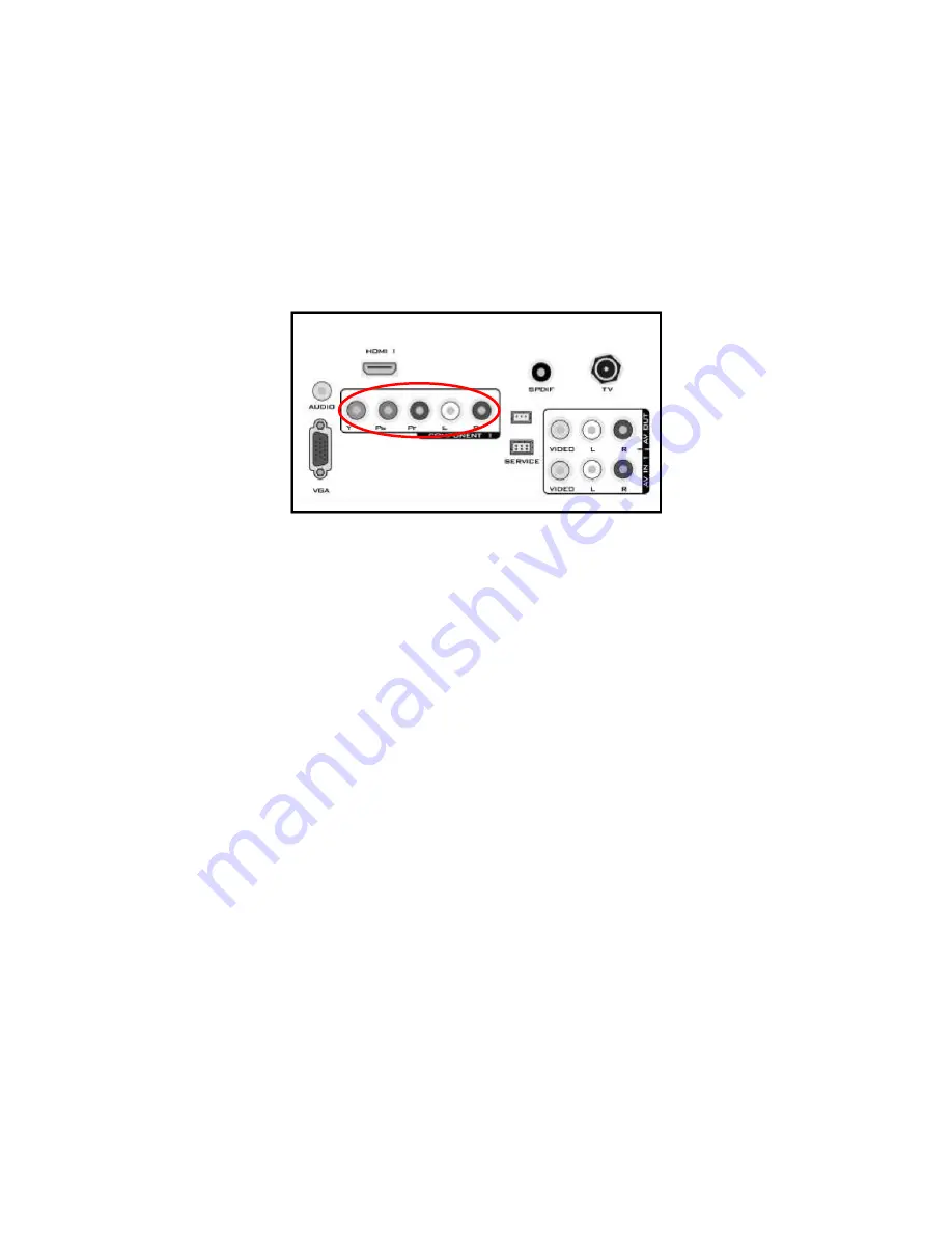
Using Component Video
Connecting your DVD Player (Better)
1. Turn off the TV and DVD player.
2. Connect the Pr (red color) connector on your DVD player to the corresponding Pr (red color) connector in the
Component at the rear of the TV.
3. Connect the Pb (blue color) connector on your DVD player to the corresponding Pb (blue color) connector in the
Component group at the rear of the TV.
4. Connect the Y (green color) connector on your DVD player to the corresponding Y (green color) connector in the
Component group at the rear of the TV.
5. Using an audio cable (red and white connectors), connect the cable to the audio output connectors associated
with the Component output on your DVD player and connect the other end to the audio connectors associated with
the Component input at the rear of the TV.
6. Turn on the TV and DVD player.
7. Select Component using the SOURCE button on the Remote control or the INPUT keypad on the side of the TV
or directly by pressing the COMP button on the Remote Control.
NOTE
Refer to your DVD player user manual for more information about the video output requirements of the product.
Содержание L22DK99U
Страница 4: ...4 1 General Specification Computer formats ...
Страница 5: ...5 Video formats ...
Страница 6: ...6 2 Operating Instructions 2 1 The Use of Remote Control ...
Страница 8: ...8 Audio Setting The Audio Setting in most source modes shows as below ...
Страница 9: ...9 Feature Setting The Feature Setting in TV mode shows as below ...
Страница 10: ...10 Installation Setting The Installation Setting in TV mode shows as below ...
Страница 18: ...18 2 4 Front Panel Control Knobs ...
Страница 22: ...22 3 Remove six screws and unplug four connectors to remove the main board ...
Страница 25: ...25 9 Remove the four screws to remove the front bezel 7 Remove the connector to remove Key Board 10 The panel ...
Страница 38: ...38 6 PCB Layout 6 1Main Board 715G3560M0F0000040 ...
Страница 39: ...39 ...
Страница 40: ...40 6 2 Power Board 715G3414P01H300010 for 22 ...
Страница 41: ...41 ...
Страница 42: ...42 715G3811P01H200030 for 26 _32 ...
Страница 43: ...43 ...
Страница 44: ...44 6 3 Inverter Board 715G3335 1 2 for 26 ...
Страница 45: ...45 715G3652P020000030 for 32 ...
Страница 46: ...46 6 4 Key Board 715G3403 1 ...
Страница 47: ...47 6 5 IR Board 715G3402 E ...
Страница 74: ...74 9 4 Key Board 715G3403 ...


