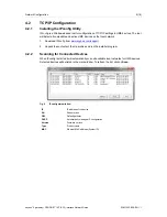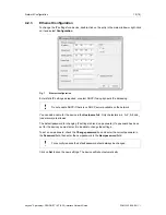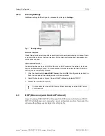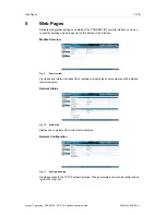
PROFINET Data Exchange
14 (18)
6.3
Data Representation (IO Data and Record Data)
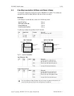
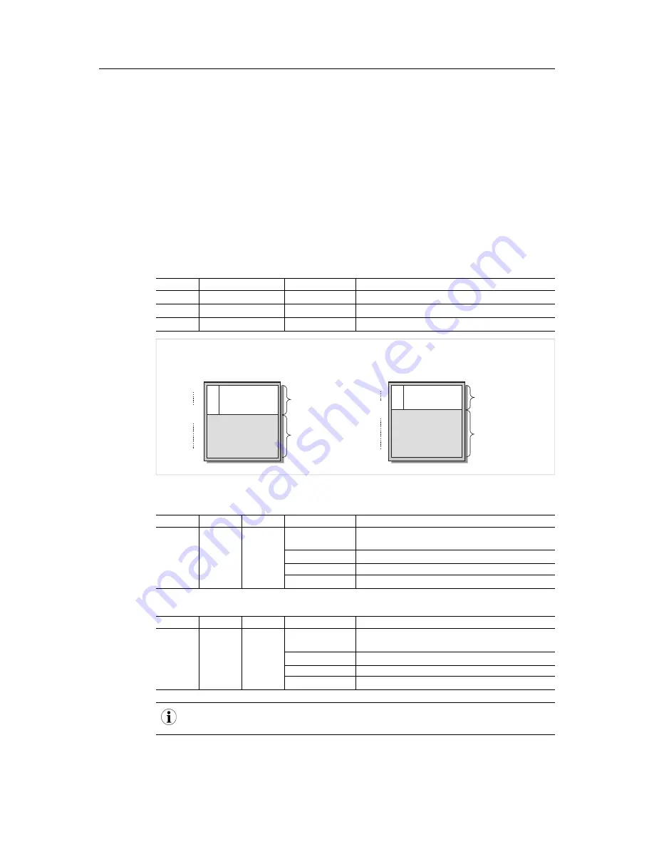
The actual I/O configuration is determined by the PROFINET IO Controller. The modules are
mapped to the Input and Output Buffers in the order of their slot number.
Example:
In this example, the data sizes have been set to the following values:
Input I/O Data Size:
208 bytes
Input Parameter Data Size:
304 bytes
Output I/O Data Size:
176 bytes
Output Parameter Data Size:
336 bytes
The following modules are specified in the IO Controller:
Slot
Module Size
Direction
Comment
0
0
-
Device Access Point (DAP)
1
176 bytes
Output
-
2
208 bytes
Input
-
INPUT BUFFER
Offset
Offset
Slot
2
1
Slot
Module size
Module size
OUTPUT BUFFER
208 byte Input
176 byte Output
0x000
0x1FF
0x000
0x0CF
Record Data Index 1000h
Record Data Index 112Fh
Record Data Index 2000h
Record Data Index 214Fh
Input I/O Data Size
(208 bytes)
Input Parameter Data Size
(304 bytes)
Output I/O Data Size
(176 bytes)
Output Parameter Data Size
(336 bytes)
0x0AF
0x1FF
0x0B0
0x0D0
Fig. 12
Input and output buffers
Input Parameter Data
API
Slot
Subslot
Index
Comment
0
0/1/2
1
1000h
First byte of the Input parameter area
(address 0x0D0 in the example above)
1001h
Second byte of the Input parameter area
…
112Fh
Last byte of the Input parameter area
Output Parameter Data
API
Slot
Subslot
Index
Comment
0
0/1/2
1
2000h
First byte of the Output parameter area
(address 0x0B0 in the example above)
2001h
Second byte of the Output parameter area
…
214Fh
Last byte of the Output parameter area
The Control Word and Status Word and the Live List are not considered in this example. For
more information, please refer to the Anybus X-gateway User Manual.
Anybus
®
X-gateway
™
PROFINET
®
IRT (2.32) Interface Network Guide
SCM-1202-028-EN 1.1

