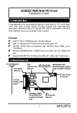
PCI Multi Serial I/O Card
3
Default: All jumpers are at “DIS” positions, no power supplied to DB9
connector
Example: If you want to 12V over pin 9 of the external DB9
connectors. Here is the jumper position for you.
1.
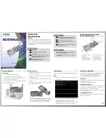
Turn the system power OFF before installation!
2.
Remove the chassis cover from your computer
3.
Locate an unused PCI slot and remove the corresponding slot
cover from computer chassis.
4.
Plug the I/O card to the unused PCI expansion slot and attached
the I/O card bracket to the computer chassis screw.
5.
Put the chassis cover back on the computer.
6.
Install the DB44M-to-DB9Mx2 Octopus Cable.
7.
Install the serial devices to the male DB9 connectors of Octopus
Cable with the correct wired RS232 cables.
4. Installing the PCI I/O Adapter
Pin 1, 4, 8 are set at “DIS”, so they won’t have power
PIN1 PIN4 PIN8 PIN9
+5V
+12V
DIS
PIN1 PIN4 PIN8 PIN9
+5V
+12V
DIS
Pin 9 has +12V power


