PCI Multi Serial I/O Card
2
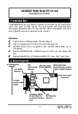
J2: Aux power connector, it can be connected to standard
power supply to p5V or +12V power to both DB9
connectors.
JP3: Power Source Selector for DB9 connectors, it is used to
select where is the device power source of +5V and +12V will
come from, from PCI golden fingers or from J2 power connector.
JP3
Description
Both +5V and 12V are
supplied from PCI slot
(Default)
Both +5V and +12V are
supplied from J2
JP5: S1 Power Pin Selector (for Port 1 DB9 connector)
JP4: S2 Power Pin Selector (for Port 2 DB9 connector)
The 2 jumpers are used to 5V or +12V to designated pin
of the DB9 connectors (JP5 for S1 and JP4 for S2). The factory
default settings are set at “DIS” location (no power supplied to
the DB9 connectors). The power can be wired to pin 1, 4, 8, or 9.
To set this jumper, locate the column where with pin number
printed (PIN1, 4, 8 or 9), move the jumper from DIS position to +5V
or +12V position. If the jumper is set at “+5V” position, then +5V
will be wired to the designated pin. If the jumper is set at “+12V”,
then +12V will be wired to the designated pin number shown
above the column.
PCI AUX
3. Jumper Settings
+5V
+12V
PCI AUX
+5V
+12V


