Anritsu NF7500 Series Скачать руководство пользователя страница 66

Chapter 3    Operation Method 

3-52 

3.17 How to Check and Save Configuration 

3.17.1  How to check configuration 

Display the non-default configuration information. 
Place the mouse cursor on the [Misc] tab at upper left of the screen. 
The pull-down menu of the Misc menu appears. Click the [Config] tab. 
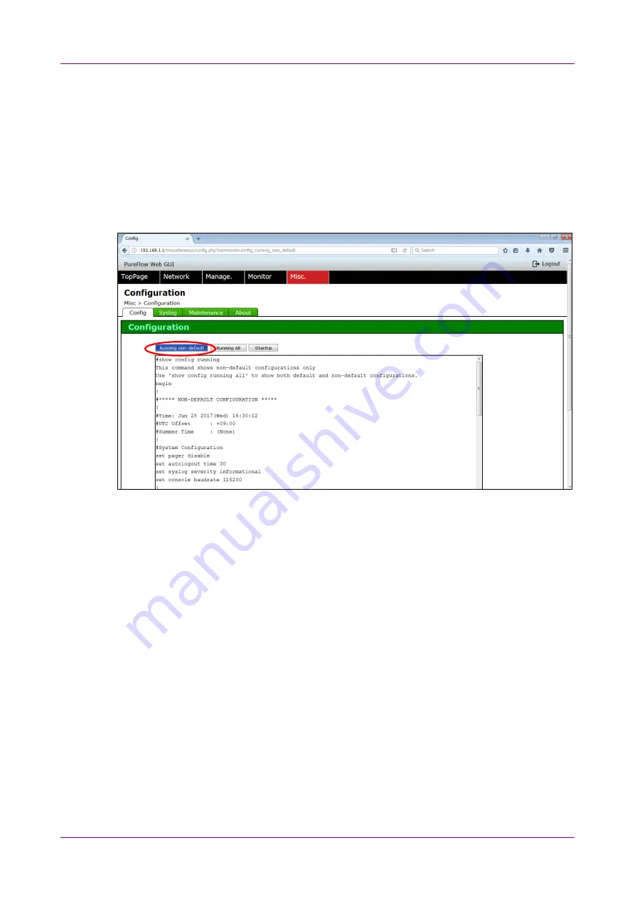
The Configuration screen appears. 
Click the [Running non-default] button. 
The non-default configuration information appears as show below. 


Содержание NF7500 Series

Страница 1: ...ebGUI Operation Manual For safe and appropriate use of the equipment please read this manual before using the equipment Additional safety and warning information is provided within the Operation Manua...

Страница 2: ...Safety Symbols Used on Equipment and in Manual The following safety symbols are used inside or on the equipment near operation locations to provide information about safety items and operation precau...

Страница 3: ...ipment contact an Anritsu Corporation Service and Sales office Contact information can be found on the safety manual Maintenance Contract Anritsu Corporation can provide a range of optional services u...

Страница 4: ...xport controlled items or not When you dispose of export controlled items the products manuals need to be broken shredded so as not to be unlawfully used for military purpose Trademark Registered Trad...

Страница 5: ...ice 2 Command Reference NF7500 W012E Describes in detail the commands used in this device 3 Configuration Guide NF7500 W013E Describes the basic features of this device and provides specific examples...

Страница 6: ...figure Scenario 3 14 3 9 Application Acceleration Settings 3 18 3 10 How to Configure Filter 3 22 3 11 How to Set Rule List 3 26 3 12 How to Perform Settings Related to Time 3 30 3 13 Setting Flow Ide...

Страница 7: ...III 1 2 3...

Страница 8: ...IV Blank page...

Страница 9: ...of the network connected terminal The WebGUI system sketch drawing is shown below WebGUI is connected from the system interface For the system interface setting method refer to PureFlow WS1 Traffic S...

Страница 10: ...emotely in the bypass connection state enabled by the network bypass function To manage this device remotely in the bypass connection state connect this device via the Ethernet port Figure 1 2 WebGUI...

Страница 11: ...ration configuration Filter configuration Rule list setting Flow identification mode setting Items related to management WebGUI enables the following settings related to the device built in time Time...

Страница 12: ...Chapter 1 Overview 1 4 Blank page...

Страница 13: ...below Using under environments other than the recommended operating environment cannot ensure the WebGUI is operated normally Additionally use the terminal that is not affected by the virus OS Windows...

Страница 14: ...Chapter 2 Operating Environment 2 2 Blank page...

Страница 15: ...3 28 3 12 How to Perform Settings Related to Time 3 30 3 12 1 How to set time zone 3 31 3 12 2 How to set daylight saving time 3 32 3 12 3 How to set SNTP 3 33 3 12 4 How to set time manually 3 35 3 1...

Страница 16: ...dicates the point to be clicked selected on the Web browser screen mark Indicates the name of the reference destination mark Indicates a proper name other than those described above mark Indicates the...

Страница 17: ...Method 3 2 Notes for Settings After settings be sure to save the setting contents by referring to 3 17 2 How to save configuration The setting detail is reflected without saving it However the setting...

Страница 18: ...Shaper NF7500 series Command Reference After the completion of system interface setting start up the Web browser and specify the IP address set in the system interface The default value of the system...

Страница 19: ...password for security reasons For login by the RADIUS authentication server enter the RADIUS server user name in the UserName column Enter the RADIUS server password in the Password column and click t...

Страница 20: ...thod 3 6 For logout click the Logout button at upper right of the screen If this screen is not operated for 5 minutes it automatically logs out Time taken until the automatic logout is 5 minutes This...

Страница 21: ...or setting the application acceleration Time This screen is used for the settings related to the time Scenario Traffic This screen is shows traffic graph of specified scenario Network Port Traffic Thi...

Страница 22: ...rio STEP 4 Configure the filter and rule list as required add channel delete channel show channel set ip channel unset ip channel show ip channel add scenario update scenario delete scenario show scen...

Страница 23: ...n Method 3 6 How to Set Channel Set the channel Place the mouse cursor on the Network tab at upper left of the screen The pull down menu of the Network menu appears Click the Channel tab The Channel S...

Страница 24: ...Chapter 3 Operation Method 3 10 1 Enter and select the parameter in the column on the left side of the screen and 2 click the Add button Check that the channel has been added as shown below 1 2...

Страница 25: ...3 6 How to Set Channel 3 11 3 Operation Method To delete the channel 3 select the relevant channel 4 Click the Delete button to delete the channel 3 4...

Страница 26: ...dress of the channel set the channel in advance 1 Select the relevant channel 2 IPv4 and IPv6 address can be set Select radio button set or unset Enter the IP address in the IPAddress column and the n...

Страница 27: ...3 7 How to Set IP Address of Channel 3 13 3 Operation Method Check that IP address has been added as shown below...

Страница 28: ...o To register the Wan Accel scenario the TCP acceleration function license is required Place the mouse cursor on the Network tab at upper left of the screen The pull down menu of the Network menu appe...

Страница 29: ...port As an example procedure for adding a scenario on the 2nd layer for port1 is described below 1 Select port1 in the Scenario Tree window on the left side of the screen and 2 click the button in gre...

Страница 30: ...tion Method 3 16 Check that the button in gray appears at the scenario on the first layer in the Scenario Tree window as shown below This button appears to indicate the existence of the scenarios on t...

Страница 31: ...cting the relevant scenario the parameter of the scenario can be checked in the Scenario Edit window To delete the scenario or change the parameter 5 select the relevant scenario To delete the scenari...

Страница 32: ...eration setting the TCP acceleration function license is required In addition configure the acceleration mode scenario prior to registration Place the mouse cursor on the Network tab at the upper left...

Страница 33: ...window and 2 click the button in green In the Application window 3 select Application and 4 enter each parameter 5 Click the Apply button If the above steps are performed for the scenario in which the...

Страница 34: ...Chapter 3 Operation Method 3 20 Check that the 6 button in gray appears at the scenario in which the application acceleration setting was registered 6...

Страница 35: ...in gray displays the application acceleration setting entry linked with the scenarios To delete the application acceleration setting first 7 select the scenario where the relevant application is set...

Страница 36: ...filter To configure the filter configure the scenario in advance Place the mouse cursor on the Network tab at upper left of the screen The pull down menu of the Network menu appears Click the Filter R...

Страница 37: ...ter in the Filter window In the Filter window 2 enter each parameter and 4 click the Add Filter button To use a rule list as a parameter 3 select the rule list and 4 click the Add Filter button For de...

Страница 38: ...Chapter 3 Operation Method 3 24 Check that the 5 button in gray appears at the relevant scenario as shown below This button appears to indicate the existence of the filters of the scenario 5...

Страница 39: ...button in gray displays the filters linked with the scenarios By selecting the relevant filter the parameter of the scenario can be checked To delete the filter or change the parameter 6 select the re...

Страница 40: ...ist group and rule list entry and set them 3 11 1 How to set rule list group Set the rule list group Place the mouse cursor on the Network tab at upper left of the screen The pull down menu of the Net...

Страница 41: ...een in the Rulelist window 2 Enter the desire name in the List Name column select Type and 3 click the Add Group button Check that the set rule list group as shown below To delete the list group 4 sel...

Страница 42: ...to set rule list entry Set the rule list entry To set the rule list entry set the rule list group in advance 1 Select the relevant rule list group 2 enter the IP address or port number in the Entry co...

Страница 43: ...utton appears to indicate the existence of the rule list entry of the scenario By clicking the button in gray the parameters of the rule list entry set in the rule list group can be checked To delete...

Страница 44: ...ettings Related to Time Perform the settings related to the current time Place the mouse cursor on the Manage tab at upper left of the screen The pull down menu of the Manage menu appears Click the Ti...

Страница 45: ...Operation Method 3 12 1 How to set time zone Set the time zone 1 Select a time zone from Time Zone in the Time Config window and 2 click the Apply button Check that TimeZone in the Current time confi...

Страница 46: ...time Set the daylight saving time In the Time Config window 1 Select Set in SummerTime 2 enter select parameters respectively and 3 click the Apply button Check that Daylight Saving Time in the Curren...

Страница 47: ...SNTP Set SNTP 1 Select SNTP in Time Mode of the Time Config window 2 Enter parameters in SNTP IP Address and SNTP Interval respectively and 3 click the Apply button Check that Mode in Current Time Con...

Страница 48: ...the SNTP server automatically at the interval of specified SNTP Interval In addition synchronization with the SNTP server can be performed at the desired timing by clicking the SNTP Sync Immediately b...

Страница 49: ...the time manually 1 Select Manual in Time Mode of the Time Config window and 2 click the Apply button 3 Check that Mode in Current Time Configuration is Manual 4 Enter the current date MM DD YYYY and...

Страница 50: ...Chapter 3 Operation Method 3 36 Check that Page Load Time in Current Time Configuration indicates the specified time as shown below...

Страница 51: ...13 Setting Flow Identification Mode Set the flow identification mode Place the mouse cursor on the Network tab in the upper left of the screen The pull down menu of the Network menu appears Click the...

Страница 52: ...ration Method 3 38 1 Specify the slot position and port number in the Filter Mode window and 2 select the field used for identification of the flow 3 Click the Set button to set the flow identificatio...

Страница 53: ...the mouse cursor on the Monitor tab at upper left of the screen The pull down menu of the Monitor menu appears Click the Scenario Traffic tab The Scenario Traffic graph screen appears as show below F...

Страница 54: ...re for selecting a scenario on the 2nd layer for port1 is described below 1 Select port1 in the Scenario Tree window and click the button in gray displays the scenarios on the 2nd layers 2 select the...

Страница 55: ...ay Traffic Graph of Scenario 3 41 3 Operation Method Click the Graph tab of the Scenario Traffic window The transmit receive traffic graph appears as shown below Check that the scenario has been chang...

Страница 56: ...Chapter 3 Operation Method 3 42 4 Range of the graph can be changed in Period 5 Period of the graph can be changed in Refresh 5 4...

Страница 57: ...play Traffic Graph of Network Port Display the traffic graph of network port Place the mouse cursor on the Monitor tab at upper left of the screen The pull down menu of the Monitor menu appears Click...

Страница 58: ...Chapter 3 Operation Method 3 44 The transmit receive traffic graph of network port in the Network Port Traffic window...

Страница 59: ...3 15 How to Display Traffic Graph of Network Port 3 45 3 Operation Method 1 Range of the graph can be changed in Period 2 Period of the graph can be changed in Refresh 2 1...

Страница 60: ...s graph To display the WAN accel sessions graph the TCP acceleration function license is required Place the mouse cursor on the Monitor tab at upper left of the screen The pull down menu of the Monito...

Страница 61: ...play WAN accel Sessions Graph 3 47 3 Operation Method First select the scenario to display the graph Click the Select Scenario tab of the WAN Accel Sessions window The scenario selection screen appear...

Страница 62: ...re for selecting a scenario on the 2nd layer for port1 is described below 1 Select port1 in the Scenario Tree window and click the button in gray displays the scenarios on the 2nd layers 2 select the...

Страница 63: ...3 16 How to Display WAN accel Sessions Graph 3 49 3 Operation Method Click the Graph tab of the WAN Accel Sessions window The WAN accel sessions graph appears as shown below...

Страница 64: ...Chapter 3 Operation Method 3 50 Check that the scenario has been changed as shown below...

Страница 65: ...3 16 How to Display WAN accel Sessions Graph 3 51 3 Operation Method 4 Range of the graph can be changed in Period 5 Period of the graph can be changed in Refresh 4 5...

Страница 66: ...lay the non default configuration information Place the mouse cursor on the Misc tab at upper left of the screen The pull down menu of the Misc menu appears Click the Config tab The Configuration scre...

Страница 67: ...on Method Display the default configuration information and non default configuration information Click the Running All button on the Configuration screen The default configuration information and non...

Страница 68: ...er 3 Operation Method 3 54 Display the configuration information at startup of the device Click the StartUp button on the Configuration screen The configuration information at startup of the device ap...

Страница 69: ...n in the internal memory Click the Save Current Configuration button at the bottom of the Configuration screen Check that the screen that shows the completion of saving appears as shown below When 5 s...

Страница 70: ...the current device operation Place the mouse cursor on the Misc tab at upper left of the screen The pull down menu of the Misc menu appears Click the Syslog tab The View Syslog screen appears Click th...

Страница 71: ...eration Click the Backup Latest button The system log information at the latest device operation appears as shown below Display the system log information at the last but one device operation Click th...

Страница 72: ...heck Module Information Check the module information of this device Place the mouse cursor on the Misc tab at upper left of the screen The pull down menu of the Misc menu appears Click the About tab T...

Страница 73: ...How to Perform Maintenance Operations Perform maintenance operations on this device Place the mouse cursor on the Misc tab on the upper left of the screen The pull down menu of the Misc menu appears...

Страница 74: ...A file selection window will open When a file is selected the file name appears on the right of the Browse button Click the Upload button The software will start being transferred to the device Do not...

Страница 75: ...ed Do not allow the power to the device to be turned off while upgrading is in progress If the power to the device is inadvertently turned off during the upgrade process the previous software version...

Страница 76: ...her than the genuine object file specified by Anritsu file name nf7500 bin Before clicking the Upload button in the above procedure make sure that the file is the genuine object file If you have uploa...

Страница 77: ...boot System window enables the Reboot button Click the Reboot button to reboot the device The following screen appears showing that the device is being rebooted After the device is rebooted open the W...

Страница 78: ...Document No NF7500 W014E Printed in Japan...

Отзывы: