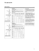
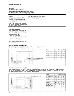
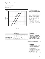


Accessories
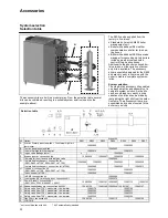
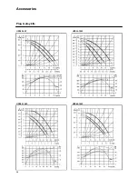
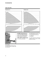
Plug & play kits
23
Kit A: 2x max. Water pressure switch
+ 1x external high limit thermostat
The kit includes a connection piece,
which can be connected the flow con-
nection of the boiler. For multiple as-
sembly variations a 90º bend is in-
cluded, to enable a connection possibil-
ity to the right or the left. (see also sec-
tion “connection possibilities”).
The connection piece is pre-assembled
with the following components:
•
2x maximum water pressure switch
•
1x manometer
•
1x high limit thermostat
All components are electrically wired,
and can be connected directly to the
terminals in the boiler. Consult the wi-
ring diagram for more details.
Kit B: max. gas pressure switch
The kit includes a gas pressure switch,
which can be connected directly to the
gas line inside the boiler. The gas pres-
sure switch is electrically wired, and
can be connected directly to the termi-
nals in the boiler. Consult the wiring
diagram for more details.
Kit C: external high limit thermostat
The kit includes a connection piece,
which can be connected the flow con-
nection of the boiler. For multiple as-
sembly variations a 90º bend is in-
cluded, to enable a connection possibil-
ity to the right or the left. (see also sec-
tion “connection possibilities”).
The high limit thermostat connection
plunge is pre-assembled on the con-
nection piece. The high limit thermostat
is electrically wired, and can be con-
nected directly to the terminals in the
boiler. Consult the wiring diagram for
more details.
Kit D: gas valve leakage tester
The kit includes a gas valve leakage
tester, which can be connected directly
to the gas valve in the boiler. The gas
valve leakage tester is electrically wi-
red, and can be connected directly to
the terminals in the boiler. Consult the
wiring diagram for more details.
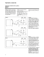
Kit E: bypass
The kit includes a bypass pump inclu-
ding connection material. The kit is to
be connected between the flow and
2nd return connection of the boiler.
The bypass pump is electrically wired,
and can be connected directly to the
terminals in the boiler. Consult the wi-
ring diagram for more details.
Kit F: wiring for room fan and exter-
nal gas valve
The kit contains the electrical wiring for
connecting an external gas valve
and/or a room fan. The electrical kit can
be easily mounted into the elctrical
panel of the boiler and be connected to
the main terminals. Consult the wiring
diagram for more details.
Содержание SH60
Страница 3: ...3 ...
Страница 7: ...Technical description Declaration of conformity 7 ...
Страница 26: ...26 UPS32 60F UPS32 120F UPS50 120F UPS65 120F Accessories Plug play kits ...
Страница 45: ......
Страница 46: ......
Страница 47: ......