


10
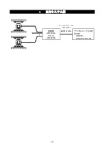
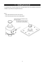
Step 4
Attach the load cell to the lower mounting bracket. When installing the load cell, adjust the cable
direction to an angle of 90 degrees to the direction where the fluctuation distance is large.
For example, in the case of a truck scale, align at an angle of 90 degrees to the traveling direction of
the vehicle.
Step 5
Lower the main girder gradually while confirming the position of the mounting bracket and load cell.
Step 6
When the mounting bracket slightly touches the load cell, adjust the position of the mounting bracket
so that the load cell stands vertically. Confirm the verticalness at two directions that differ by 90°. Make
fine adjustments to the position of the lower or upper mounting bracket so that the tilt angle of the load
cell is 0.5° or less.
Direction where fluctuation distance is large
Main
girder
Upper mounting
bracket
Stopper column
Base plate
Load cell
Lower mounting
bracket
M16 bolt and
spring washer
Front view
Side view


