background image

6.  About the mounting brackets 

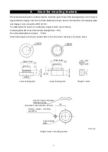
When manufacturing the mounting brackets, make the guide holes of the bearing plates to which load is 
applied and the stopper column are of the dimensions shown below. The hardness of the bearing plate 
and stopper column should be HRC 32~38. 
The fastening bolts used for mounting the stopper column are as follows. 
Fastening bolts: M12 hex bolts (Tensile strength class: 10.9) 
Recommended tightening torque:  76 Nm 
Attach the stopper column at a position 50 mm from the center, referring to the figure below. 


Unit: mm 

Taper angle 

Lower bearing plate 

Upper bearing plate 

Stopper column 

Direction where fluctuation 

distance is large 

(Example: Travel direction of truck) 

Stopper column mounting 

hole (M12) 

Lower bearing 

plate 

Stopper column mounting position 

26 or

 mor

Taper angle 

26 or

 mor

15° 

15° 

Содержание LCCD20 Series

Страница 1: ...ompression Digital Load Cell 取扱説明書 Instruction Manual LCCD20T010 K LCCD20T010N K LCCD20T020 K LCCD20T020N K LCCD20T030 K LCCD20T030N K LCCD20T010 KC6 LCCD20T010N KC6 LCCD20T020 KC6 LCCD20T020N KC6 LCCD20T030 KC6 LCCD20T030N KC6 1WMPD4003396A ...

Страница 2: ... エー アンド デイ 株式会社エー アンド デイの許可なく複製 改変などを行なうことはできません 2017 A D Company Limited All rights reserved No part of this publication may be reproduced transmitted transcribed or translated into any language in any form by any means without the written permission of A D Company Limited The contents of this publication and the specifications of the instrument covered by this publication are subject to change f...

Страница 3: ...1 日本語 目次 1 LCCD20 シリーズ 圧縮型デジタルロードセル一覧 2 2 使用上の注意事項 2 2 1 施工に必要な条件 2 2 2 施工上の注意 3 2 3 トラックスケールの設置例 3 2 4 設置作業上の注意 4 2 5 日常点検 4 3 概要 4 4 仕様 5 5 外観図 6 6 マウント金具について 7 7 設置方法 8 8 主なシステム例 12 ...

Страница 4: ...精度等級 C4 LCCD20T010N KC6 金具なしタイプ 定格容量 98 07kN 10t 精度等級 C6 LCCD20T020N KC6 金具なしタイプ 定格容量 196 1kN 20t 精度等級 C6 LCCD20T030N KC6 金具なしタイプ 定格容量 294 2kN 30t 精度等級 C6 2 使用上の注意事項 本製品を正しく安全にお使いいただくために 以下の注意事項を熟読して下さい ここに記載されてい る内容は 機器の安全な取り扱いの主な事柄をまとめたものです 機器特有の注意事項については 以 降の本文中にも記載しておりますので ご使用前に本書をご一読ください 2 1 施工に必要な条件 ロードセルを取り付ける構造物の強度は 荷重に十分耐えられるように設計して下さい 基礎のベースプレートは平面かつ水平に設置して下さい ベースプレート相互間の水平度 3 mm 以内 目安 ベ...

Страница 5: ...ください ロードセルケーブルの誤配線には注意して下さい 誤配線が原因で機器の損傷を招く恐れがあり ます 通電している機器にロードセルの接続はしないで下さい また 通電前に接続に誤りが無いかよく 確認してください ロードセルに強い衝撃を与えないで下さい 最大印加電圧を超える電圧をロードセルに加えないで下さい ロードセル内部を破損する恐れが あります ロードセルを装着したまま溶接作業を行う時は ロードセルに電流が流れないよう溶接個所の近 くにアースを接続するようにしてください 2 3 トラックスケールの設置例 基礎の施工は入念に行われていること トラックの進行方向 振れ止めストッパー ロードセルケーブルは電線管で保護してください 振れ止めストッパーの隙間は5mm 以下としてください 推奨は2 3mm です ストッパー用補強板 ベースプレート ベースプレート相互間の水平度 3mm 以内 ベースプ...

Страница 6: ...間は適正か ゴミ 泥などは詰まっていないか ピットには水が溜まっていないか ロードセルをピット内に設置の場合 ロードセル マウント金具に付着物は無いか 取り付けボルトに緩みは無いか ストッパーコラムに緩みは無いか ロードセルケーブルにたるみはあるか ケーブルの接続に緩みは無いか 漏電は無いか 3 概要 LCCD20 シリーズ圧縮型デジタルロードセルは トラックスケールに適した 98 07kN 10t 294 2kN 30t の定格容量を有する高性能の圧縮型ダブルコンベックスタイプデジタルロードセ ルです 弊社デジタルロードセル用インジケータとの組み合わせにより調整作業を簡単 スピーディーに 行うことができます ロードセル本体は密閉構造で保護等級は IP68 となっており 過酷な環境でも安心してお使いいた だけます 小型設計なので 設置 メンテナンス作業が楽に行えます 注意 ロードセルは精度...

Страница 7: ... づく精度等級 C ロードセル検定 目量の最大数 4000 6000 湿度記号 CH 最小測定量 Emin 0 kg 最大容量 Emax 10t 20t 30t 10t 20t 30t 許容過負荷 Elim 15t 30t 45t 15t 30t 45t 最小ロードセル検 定目量 Vmin 1kg 2kg 3kg 1kg 2kg 3kg 定格出力 R O 10000 5 20000 10 30000 15 10000 5 20000 10 30000 15 総合誤差 0 025 R O 0 016 R O 温度補償範囲 10 40 推奨印加電圧 8VDC 最大印加電圧 12VDC 零点の温度影響 0 019 R O 10 Typ 出力の温度影響 0 010 Load 10 Typ 出力信号 RS 485 2 線式 ケーブル太さ 長さ 4 芯シールドケーブル φ8 12m 保護等級 IP68...

Страница 8: ...6 5 外観図 上側ダストシール 4 芯シールドケーブル アース端子 M4 下側ダストシール ストッパーコラム 単位 mm 上下共通 力 力 ...

Страница 9: ... 耐圧盤 ストッパーコラムの硬さは HRC32 38 としてください また ストッパーコラムの取り付けに使用する固定用ボルトは次の通りです 固定用ボルト M12 の六角ボルト 強度区分 10 9 推奨締め付けトルク 76Nm ストッパーコラムの取付位置は以下の図を参考に中心から 50mm の位置に取り付けてください ストッパーコラム 単位 mm 26以 上 15 15 ストッパーコラム取付位置 テーパー角度 テーパー角度 下耐圧盤 上耐圧盤 下耐圧盤 揺動距離が大きい方向 例 トラックの進行方向 ストッパーコラム取付穴 M12 26以 上 ...

Страница 10: ...8 7 設置方法 金具付属タイプを基準に記載していますが 金具なしタイプもこの設置方法を参考にして設置して下さ い 手順 ロードセル上部にダストシール 上側 をはめ込みます マウント金具 下 にダストシール 下側 をはめ込みます 円径が大きい方がロードセル側のダストシール 円径が小さい方が金具側のダストシール ...

Страница 11: ...り付けに使用するボルトの推奨締め付けトルクは次の通りです 参考にしてくだ さい M12 六角ボルト 76Nm 手順 図を参考にマウント金具 下 をベースプレートに マウント金具 上 を主桁にそれぞれ仮止めして ください 仮止めには M16 ボルトとスプリングワッシャを使用して下さい マウント金具の向きは取り付け前にあらかじめ設置時と同じ方向に合わせます 固定用六角ボルト ストッパーコラム ストッパーコラム取付穴 揺動距離が大きい方向 例 トラックの進行方向 揺動距離が大きい方向と 同じ方向 にある穴位置に取り付ける 揺動距離が大きい方向 主桁 ストッパーコラム ベースプレート マウント金具 M16 ボルトと スプリングワッシャ マウント金具 ...

Страница 12: ...クスケールでは車両の進行方向に対し直角になるようにあわせてください 手順 マウント金具とロードセルの位置を確認しながら 主桁を徐々に降ろしてください 手順 マウント金具がロードセルに軽く当たりましたら ロードセルが垂直に立つようにマウント金具の位 置を調整します 垂直の確認は 90 異なる 2 方向から行ってください ロードセルの傾き角が 0 5 以下となるように下側 上側どちらかのマウント金具の位置を微調整します 揺動距離が大きい方向 主桁 ストッパーコラム ベースプレート マウント金具 ロードセル マウント金具 側面 正面 M16 ボルトと スプリングワッシャ ...

Страница 13: ...m ハイテンションボルト使用時 200Nm 手順 本ロードセルにはサージ保護用のアースストラップが 2 本付属されています ロードセルの設置が完了したら それぞれ図を参考にアースストラップを取り付けてください アースストラップの固定に使用するボルトの推奨締め付けトルクは次の通りです 参考にしてくださ い CAP ボルト M8 12 5Nm 十字穴付きなべ小ねじ M4 1 5Nm アーストラップ取付穴 上下共通 菊座 アースストラップ 5 5 x 30 cm CAP ボルト M8 x 12 CAP ボルト M8 x 12 菊座 アースストラップ 5 5 x 20 cm 十字穴付きなべ小ねじ M4 x 12 ...

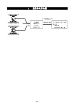
Страница 14: ...12 8 主なシステム例 ロードセルケーブル AX KO3217 接続箱 AD4388 4 または AD4388 6 最大延長 200m デジタルロードセル用 指示計 AD4353 AD4329A DLC 等 ...

Страница 15: ...rements for construction 2 2 2 Precautions for construction 3 2 3 Setup example for truck scale 3 2 4 Precautions for installation 4 2 5 Maintenance 4 3 Introduction 4 4 Specifications 5 5 External dimensions 6 6 About the mounting brackets 7 7 Installing the load cell 8 8 Examples of major systems 12 ...

Страница 16: ...ing brackets rated capacity 294 2 kN 30 t accuracy class C6 2 Precautions Please read the following notes carefully in order to use this product correctly and safely The contents described here summarize the main matters regarding safe handling of equipment Notes specific to individual equipment are also described in the following text so please read this document before use 2 1 Requirements for c...

Страница 17: ...e equipment Do not connect the load cell to energized equipment Also make sure that there is no error in connection before energizing Do not apply a strong shock to the load cell Do not provide voltage to the load cell exceeding the maximum applied voltage The inside of the load cell may be damaged if that is done When performing welding work with the load cell attached connect the ground near the...

Страница 18: ...of deposits Are the mounting bolts tight Is the stopper column tight Is there slack in the load cell cable Are cable connections tight Is the equipment free of electric leakage 3 Introduction The LCCD20 series compression type digital load cell is a high performance compression type double convex type digital load cell with rated capacity of 98 07 kN 10 t to 294 2 kN 30 t suitable for truck scales...

Страница 19: ... t 30 t 45 t 15 t 30 t 45 t Minimum verification interval Vmin 1 kg 2 kg 3 kg 1 kg 2 kg 3 kg Rated output R O 10000 5 20000 10 30000 15 10000 5 20000 10 30000 15 Combined error 0 025 R O 0 016 R O Compensated temperature range 10 C 40 C Recommended excitation voltage 8VDC Maximum excitation voltage 12VDC Temperature effect on zero balance 0 019 R O 10 C Typ Temperature effect on span 0 010 Load 10...

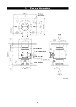
Страница 20: ...6 5 External dimensions Both plates Upper dust seal 4 core shielded cable Unit mm Ground terminal M4 Stopper column Lower dust seal Support Load ...

Страница 21: ...ting the stopper column are as follows Fastening bolts M12 hex bolts Tensile strength class 10 9 Recommended tightening torque 76 Nm Attach the stopper column at a position 50 mm from the center referring to the figure below Unit mm Taper angle Lower bearing plate Upper bearing plate Stopper column Direction where fluctuation distance is large Example Travel direction of truck Stopper column mount...

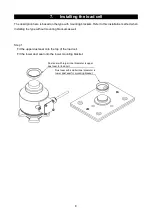
Страница 22: ...od when installing the type without mounting brackets as well Step 1 Fit the upper dust seal onto the top of the load cell Fit the lower dust seal onto the lower mounting bracket Dust seal with larger inner diameter is upper dust seal for load cell Dust seal with smaller inner diameter is lower dust seal for mounting bracket ...

Страница 23: ... mounting bracket to the base plate and the upper mounting bracket to the main girder respectively referring to the figure shown below To temporarily secure them use M16 bolts and spring washers Before mounting align the mounting brackets in the same direction as at installation Hex head bolt for securing Stopper column Attach to the hole in the direction where fluctuation distance is large Stoppe...

Страница 24: ... position of the mounting bracket and load cell Step 6 When the mounting bracket slightly touches the load cell adjust the position of the mounting bracket so that the load cell stands vertically Confirm the verticalness at two directions that differ by 90 Make fine adjustments to the position of the lower or upper mounting bracket so that the tilt angle of the load cell is 0 5 or less Direction w...

Страница 25: ...surge protection are included with this load cell When installation of the load cell is completed please attach the earth strap referring to the figures The recommended tightening torque of the bolt used to secure the ground strap is as follows Please use this for reference CAP bolt M8 12 5 Nm Small pan screw with crosshole M4 1 5 Nm Earth strap mounting hole Vertical common CAP bolt M8 x 12 Tooth...

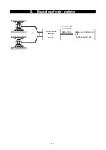
Страница 26: ...12 8 Examples of major systems Load cell cable AX KO3217 Junction box AD4388 4 or AD4388 6 Indicator for digital load cell AD4329A DLC etc Up to 200 m ...

Страница 27: ...ngdeungpo gu Seoul 07331 Korea 전화 82 2 780 4101 팩스 82 2 782 4264 OOO A D RUS OOO ЭЙ энд ДИ РУС Почтовый адрес 121357 Российская Федерация г Москва ул Верейская дом 17 Юридический адрес 117545 Российская Федерация г Москва ул Дорожная д 3 корп 6 комн 8б 121357 Russian Federation Moscow Vereyskaya Street 17 тел 7 495 937 33 44 факс 7 495 937 55 66 A D Instruments India Private Limited 509 Udyog Viha...

Страница 28: ......

Отзывы: