UG-015
Evaluation Board User Guide
Rev. 0 | Page 6 of 12
INERTIAL SENSOR EVALUATION SYSTEM GRAPHICAL USER INTERFACE
CONFIGURATION TAB
When the system is set up and configured, press
SW2
, which
is shown in Figure 9, to reset the ISEB and have it detect the
currently connected satellite. This must be done when the
satellite connected to the ISEB is replaced by a satellite of a
different part only; replacing the satellite with a satellite for
the same part, that is, an EVAL-ADXL345Z-S with another
EVAL-ADXL345Z-S, does not require
SW2
to be pressed.
The inertial sensor evaluation system GUI is opened by executing
the
ADXL345 Evaluation GUI.exe
file located in the /
ADXL345
Evaluation GUI
/
folder. To exit the GUI, use the
Stop VI
button to
disconnect from the ISEB. Then exit the application by selecting
File
and
Exit
or by pressing
Ctrl+Q
.
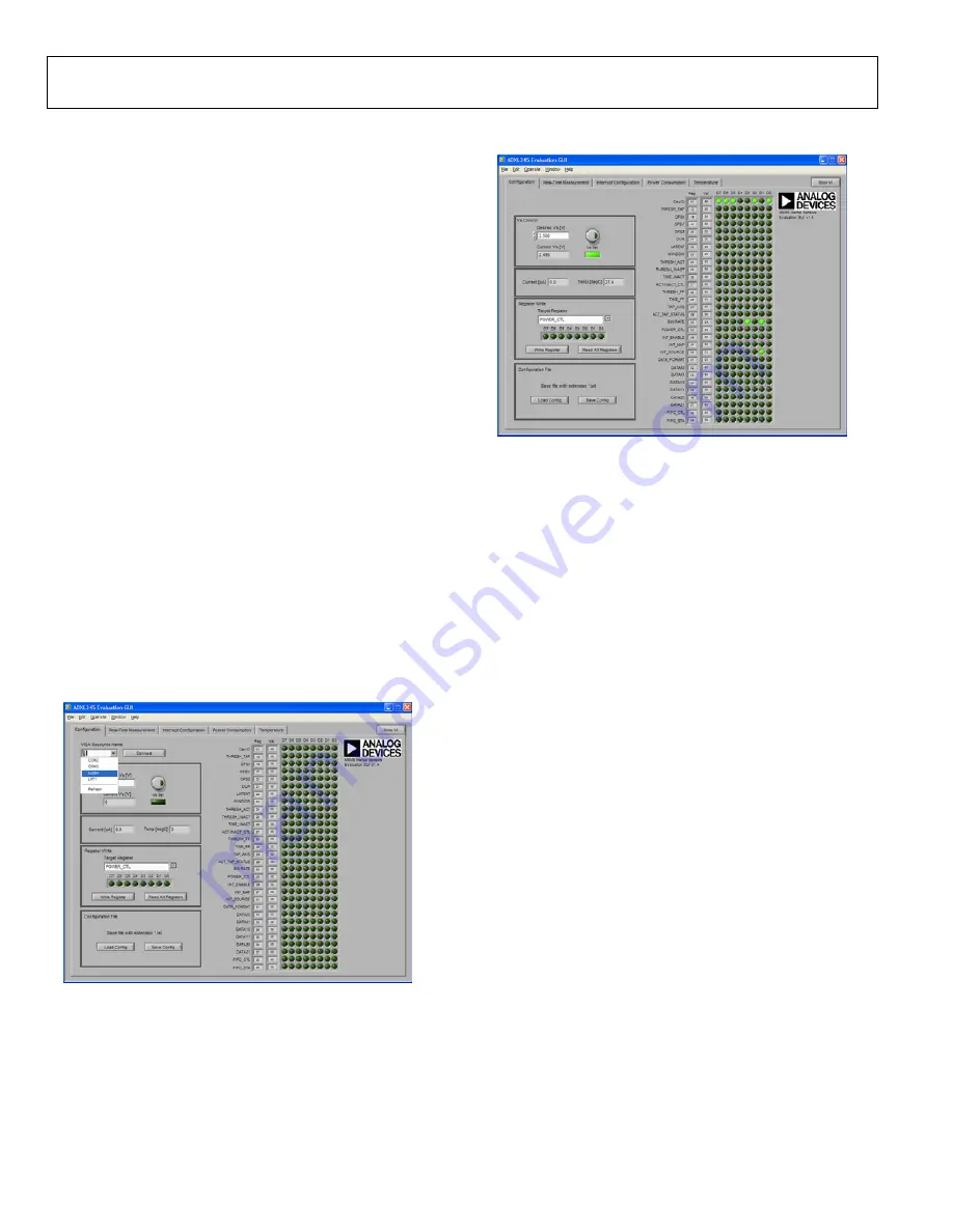
The first screen brought up is the
Configuration
tab (see Figure 10).
This screen is used for manual configuration of the sensor, for
setting up the communication port between the PC and ISEB,
and for setting the sensor voltage values. Configuration register
values can be saved and reloaded.
It is important to note that the register settings entered on this
screen are independent from other GUI screens. Each screen
requires a different register setup, and any values that can be
altered are made available for that particular screen.
With the
Configuration
tab open, select the correct COM port
for the ISEB from the
VISA Resource Name
menu (see Figure 10).
The correct COM port can be found by checking the
Device
Manager
for the
ADI Inertial Sensor Evaluation System
under
the
Ports (COM & LPT)
selection.
08
11
9-
0
07
Figure 10. Selecting the Correct COM Port for the ISEB
After selecting the COM port, click on
Connect
to connect to
the ISEB. This causes the indicator under
Vs Set
to light up and
update the
Current Vs [V]
value, verifying that the board is
connected (see Figure 11).
08
11
9-
0
08
Figure 11. ISEB Connected to PC
Clicking the round button above
Vs Set
causes the supply
voltage, V
S
, of the ADXL345 to be updated based on the value
in the
Desired Vs [V]
box. The
Current [μA]
and
Temp [degC]
boxes are also updated whenever the
Vs Set
button is clicked.
Read the contents of the ADXL345 registers by clicking the
Read All Registers
button in the
Register Write
box. This
action updates all register values and indicators on the right side
of the screen. Figure 11 depicts a sensor that is powered on with a
DevID of 0xE5, a BW/RATE value of 0x0A, and an INT_SOURCE
value of 0x02. All other registers remain in their default state of 0x00.
To write a value to a register, select the register from the
Target
Register
menu and click the D7 through D0 indicators to set the
value. If an indicator is lit, the value written to that bit is a Logic
1, whereas an unlit indicator indicates a Logic 0. When the register
is configured correctly, click the
Write Register
button to send the
value to the ADXL345. Note that the D7 through D0 indicators
under
Target Register
are not updated based on the value stored in
that register.
To save a configuration, click the
Save Config
button in the
Configuration File
box (see Figure 11). Save the file with a
.txt extension. After a configuration is saved, you can load the
configuration back into the device by clicking the
Load Config
button and selecting the configuration file.


