EVAL-SSM4567Z User Guide
UG-704
Rev. 0 | Page 7 of 23
EVALUATION BOARD SOFTWARE QUICK START PROCEDURES
HARDWARE ONLY QUICK START
The evaluation board comes configured for single 3.5 V to
5 V dc input, 48 kHz optical SPDIF input, and standalone
operation mode of the
SSM4567
. To operate the board with this
quick start configuration
1.
Connect power to J3 and J4.
2.
Connect the speaker load to J11.
3.
Connect the optical SPDIF cable to the optical jack.
4.
Apply power to the evaluation board.
5.
Start the SPDIF digital audio stream.
6.
Press the SPDIF reset switch, S1.
See Figure 2 for the jumper settings.
SSM4567
CONTROL SOFTWARE SETUP
Do not connect the USBi (
EVAL-ADUSB2EBZ
) to the
computer until the software is installed. The
SSM4567
software
interface (SigmaStudio™) requires Microsoft® .NET Framework
(Version 2.0 or later). The installer automatically downloads it if
.NET Version 2.0 is not previously installed.
A graphical user interface for the
SSM4567
has been created
in the Analog Devices, Inc.,
SigmaStudio
environment.
SigmaStudio must first be
downloaded
and installed on your
PC.
SSM4567
USB DRIVER INSTALLATION
Before connecting the USBi (
EVAL-ADUSB2EBZ
) evaluation
board to a PC or notebook, the following procedure may need
to be completed. (This procedure only needs to be executed
once on each computer that uses the
SSM4567
software. Skip
this procedure if you previously installed any SigmaStudio or
USBi related drivers from Analog Devices.)
Ensure that the Cypress (CYUSB) USB driver is installed during
the SigmaStudio installation. If you need to verify installation,
you can find the driver on your computer in this location:
C:\Program Files\Analog Devices\SigmaStudio x.x\USB
drivers\x86 (or x64)\dpinst.exe
Note that the parentheses indicate alternate folder names
depending on your hardware. In addition, x.x refers to the
version of SigmaStudio installed.
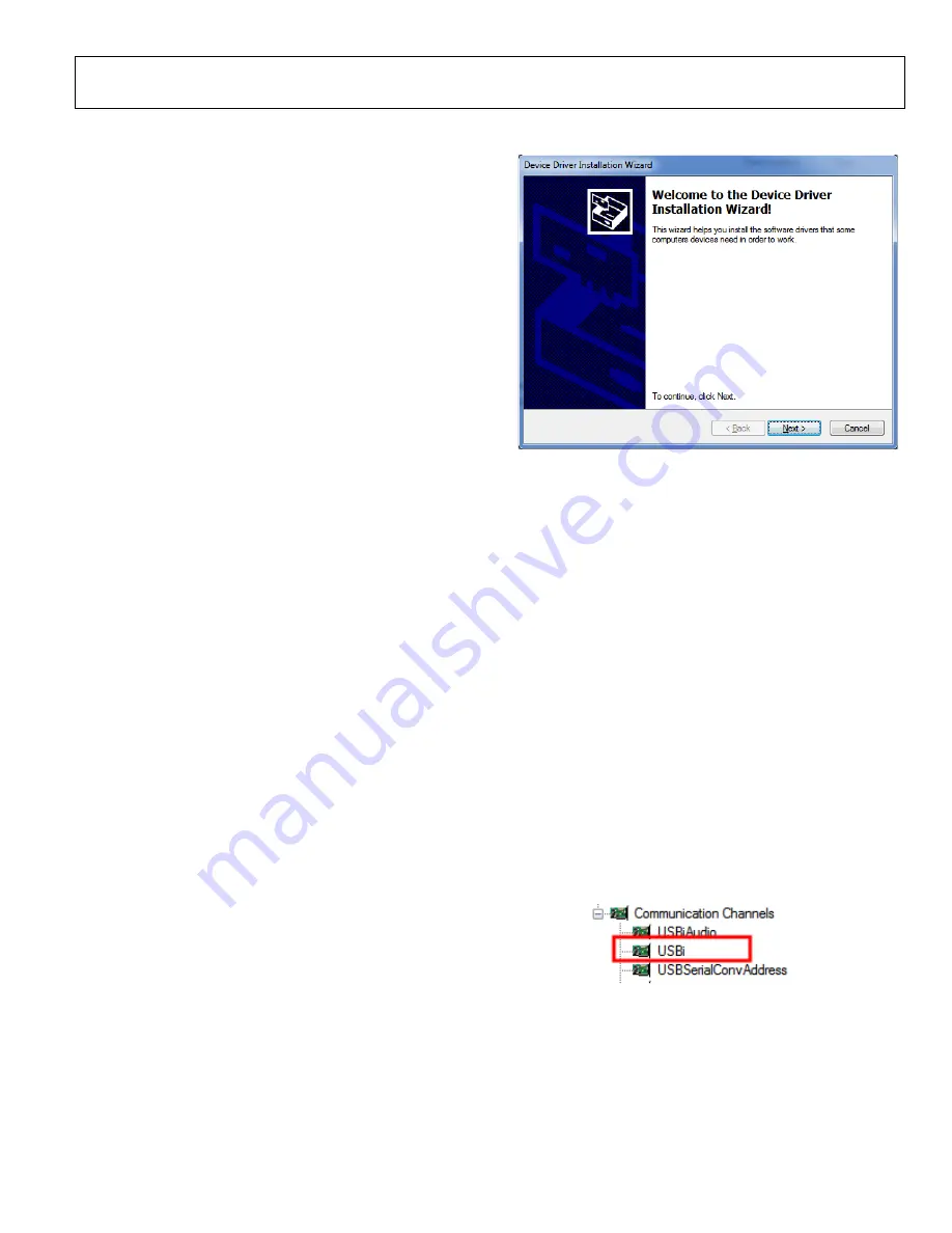
Figure 10. Device Driver Installation Wizard
INITIAL
SSM4567
HARDWARE SETUP
To allow the
SSM4567
software to control the
SSM4567
evaluation board, make a few simple jumper connections as
follows:
1.
Connect the SEL to HIGH (J12) and ADDR to LOW (J9),
and short R22 (install J13). The purpose of this is to set the
SSM4567
to work under I
2
C control mode.
2.
Remove any jumpers on J20 and J21.
3.
Install jumpers on J16 to select the digital audio input
to the
SSM4567
from either an external source or the
SPDIF input. The SPDIF input signals are labeled as INT
(internal). See Figure 4 or Figure 5 for details.
SOFTWARE INSTRUCTIONS
Complete the following instructions after SigmaStudio and the
USBi driver installation.
1.
Connect the
EVAL-ADUSB2EBZ
to your PC using the
USB cable.
2.
Launch SigmaStudio on the PC.
3.
Click
File>New Project
to start a new GUI project file, and
then find
USBi
under
Communication Channels
.
Figure 11. Location of USBi GUI
4.
Drag and drop
USBi
to the
Hardware Configuration
.
12378-
0
1
1
12378-
012


