UG-1462
User Guide
Rev. 0 | Page 6 of 18
EVALUATION BOARD SOFTWARE FOR SPI INTERFACE
INSTALLING THE SOFTWARE
The EVAL-ADGM1004SDZ uses the Analog Devices
software is a
desktop software application that allows the evaluation and
control of multiple evaluation systems.
software installer installs the necessary SDP drivers
and .NET Framework 4 by default. Install the
software
board to the EVAL-ADGM1004SDZ.
software and access to full instructions on how to
install and use the software on the Analog Devices website at
When the installation is finished, the
software starts and
the EVAL-ADGM1004SDZ plugins appear.
INITIAL SETUP
To set up the EVAL-ADGM1004SDZ, take the following steps:
1.
Change the position of the P1, P2, P3, and P4 links to SDI,
CS, SCLK, and SDO, respectively.
2.
Change the MODE link position from PIN to SPI and keep
the EXTD_EN link position set to INT.
3.
Connect the EVAL-ADGM1004SDZ to the
board,
and connect the
board to the PC via the USB cable.
4.
Power up the EVAL-ADGM1004SDZ as described in the
Power Supply section.
5.
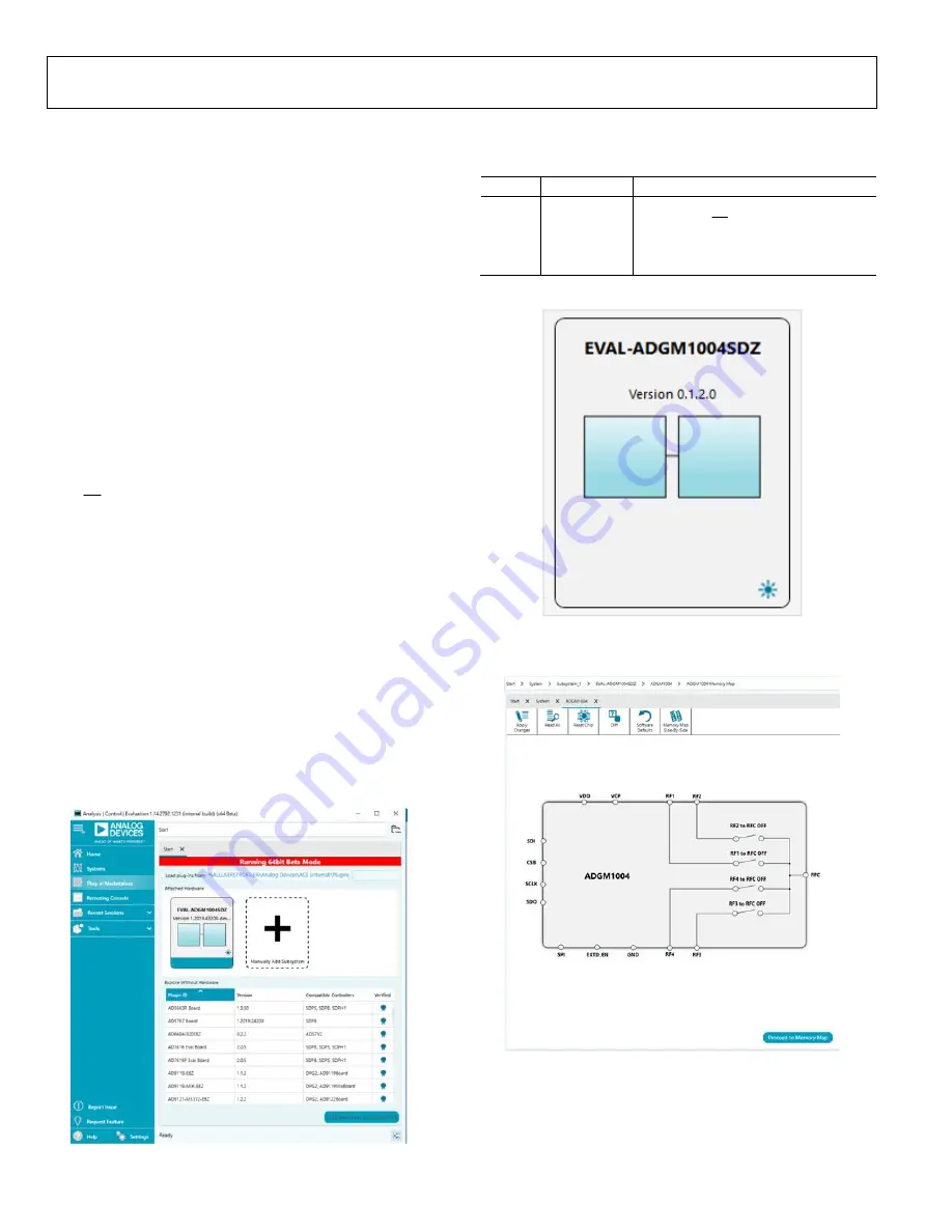
Run the
software. The EVAL-ADGM1004SDZ
plugins appear in the
Attached Hardware
section of the
Start
tab (see Figure 2).
6.
Double click the
EVAL-ADGM1004SDZ
plugin to open
the
EVAL-ADGM1004SDZ
view in Figure 3.
7.
chip to access the chip block
diagram (see Figure 4). This diagram provides a basic
representation of the EVAL-ADGM1004SDZ functionality.
The main functions are labeled in Figure 4.
17
271
-0
20
Figure 2. EVAL-ADGM1004SDZ Plugin Startup Window
Table 5. SPI Interface Link Descriptions
Link Position Description
P1
SDI
Serial data input (SDI) pin
P2 CSB
Chip select (CS) pin
P3
SCLK
Clock input (SCLK) pin
P4 SDO
Serial
data output (SDO) pin
1
727
1-
00
2
Figure 3. Evaluation Board View of the EVAL-ADGM1004SDZ Plugin
1
727
1-
00
3
Figure 4. Chip Block Diagram View of the EVAL-ADGM1004SDZ Plugin


