UG-1135
Rev. 0 | Page 15 of 45
2.
Connect the filter in series between the
Asrc Input
block
and the
Spdif Output
blocks so that the filter can be applied
to the signals passing through the DSP. The completed signal
flow resembles Figure 51.
15
789-
052
Figure 51. Completed Signal Flow
3.
Click the
Link/Compile/Download
button (see Figure 28)
or press F7 to compile the signal flow and download it to the
hardware. The audio signal passes from the S/PDIF receiver
through the ASRCs into the DSP and the EQ filter, and then
out on the S/PDIF transmitter. To change the settings of the
EQ filter, click the blue icon at top of the block. To change
the filter gain in real time while the project is running, drag
the control slider in
CONTROLLING VOLUME WITH A POTENTIOMETER
The 10-bit auxiliary ADC on the
can eliminate the
need for a microcontroller in many applications by using analog
control signals as user interface devices. As an example, the EVAL-
ADAU1466Z includes two 10 kΩ linear potentiometers connected
to Channel AUXADC0 and Channel AUXADC1. These can be
used as an inexpensive, versatile, and physical way to control
parameters such gain, filter corner frequency, slew rate, and
compression level. The following example demonstrates how a
potentiometer can be configured as a stereo volume control.
1.
Create a new project in
, and use the
Hardware Configuration
tab to use an
describe above in the Setting Up Communications in
SigmaStudio section.
2.
Add an input and two output blocks as described in the
Creating a Basic Signal Flow section.
3.
Add an
Auxiliary ADC Input
block to the project space as
follows:
a.
From the
IO
>
GPIO
>
Input
folder, click
Auxiliary
ADC Input
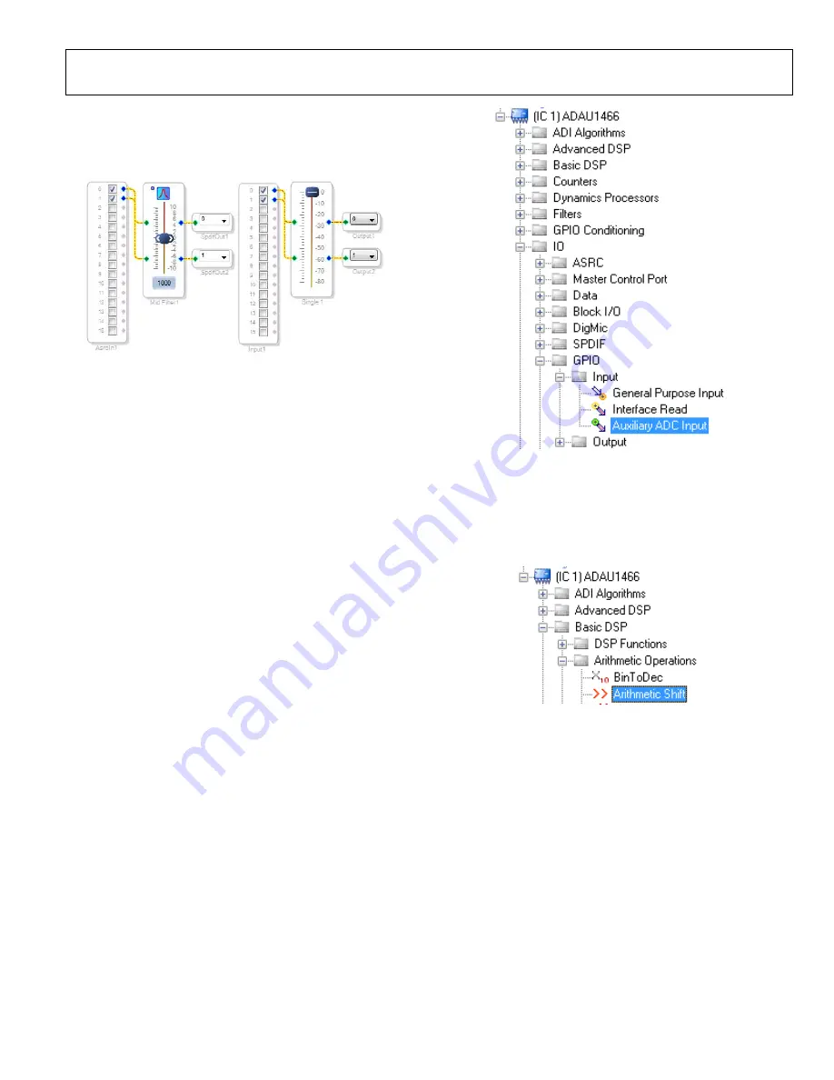
(see Figure 52) and drag it into the project
space to the right of the toolbox.
1578
9-
154
Figure 52. Auxiliary ADC Input Block Selection
4.
Add an
Arithmetic Shift
block to the project space as
follows:
a.
From the
Basic DSP
>
Arithmetic Operations
folder,
click
Arithmetic Shift
(see Figure 53) and drag it into
the project space to the right of the toolbox.
157
89-
1
55
Figure 53.
Arithmetic Shift
Block Selection
b.
The arithmetic shift block performs a bitwise right shift
or left shift. Click the blue button to select the direction.
Ensure the block is performing a left shift. The block
appears as shown in Figure 58.
c.
To set the number of bits by which the input are shifted
to 14, click and type in the yellow text box. The block
appears as shown in Figure 58.
Содержание EVAL-ADAU1466Z
Страница 37: ...EVAL ADAU1466Z User Guide UG 1135 Rev 0 Page 37 of 45 15789 087 Figure 96 EVAL ADAU1466Z Layout Top Assembly ...
Страница 38: ...UG 1135 EVAL ADAU1466Z User Guide Rev 0 Page 38 of 45 15789 088 Figure 97 EVAL ADAU1466Z Layout Top Copper ...
Страница 39: ...EVAL ADAU1466Z User Guide UG 1135 Rev 0 Page 39 of 45 15789 089 Figure 98 EVAL ADAU1466Z Layout Ground Plane ...
Страница 40: ...UG 1135 EVAL ADAU1466Z User Guide Rev 0 Page 40 of 45 15789 090 Figure 99 EVAL ADAU1466Z Layout Power Plane ...
Страница 41: ...EVAL ADAU1466Z User Guide UG 1135 Rev 0 Page 41 of 45 15789 091 Figure 100 EVAL ADAU1466Z Layout Bottom Copper ...


