


Preliminary Technical
Data
Rev. PrA | Page 60 of 82
CLOSED LOOP GAIN CONTROL (CLGC)
CLGC OVERVIEW
Closed Loop Gain Control (CLGC) is a closed-loop tracking calibration which adjusts front end Tx attenuations to maintain a
constant desired gain in the Tx path from baseband input to PA output such that the PA output power is constant with respect to
changes in temperature or other variations. The desired Tx gain is set by adjusting the Tx front end attenuation such that the PA
output reaches the desired power with the maximum nominal level of the baseband signal. The digital swing of the baseband
signal is not affected, since the attenuation is applied on the analog front end of the Tx channel.
The PA output power may fluctuate around the target level over the time due to temperature changes, and other factors, given a
constant Baseband signal level. The CLGC can help reduce the fluctuation and meet the standards’ and regulatory requirements
(e.g., +/- 2 dB fluctuation is required by LTE/5GNR standard). The Baseband signal level may change significantly due to the
dynamics of power control and traffic load in a network (e.g., dynamic range can be up to 20 dB in LTE). The CLGC can help keep
the output power linearly proportional to the baseband signal level.
ELEMENTS OF CLGC
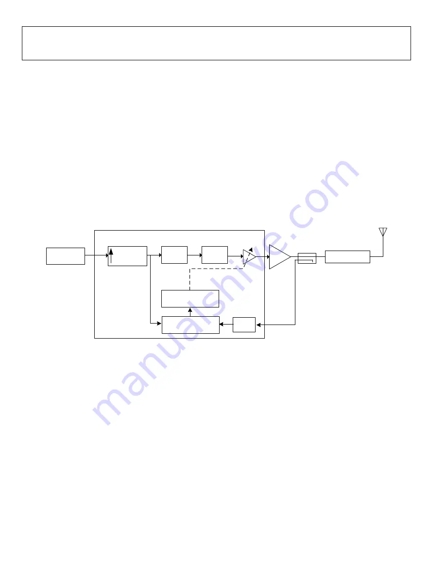
Shown below in Figure 63 is a simplified block diagram of the ADRV9025 CLGC system. In a nutshell, the CLGC algorithm
observes the transmit data(x(n)), the post PA observation data(y(n)) and adjusts the transmit front end attenuation such that the
overall loop gain (ORx data / Tx data) remains constant.
Interpolation
1,2,4
Tx
PA
FILTER/DUPLEXER
ORx
ARM-C
Data From
CFR
ADRV9025 CLGC
Firmware
DPD
Actuator
Tx FE Attenuation
Tx Atten Control
x(n)
y(n)
Capture Engine
Figure 63. ADRV9025 CLGC Simplified Block Diagram
The elements of the CLGC system are described below
•
Transmit Datapath
– The digital baseband signal from the ADRV9025 de-framer output goes through a Crest Factor
Reduction(CFR) block for reduction of the overall peak to average ratio of the signal followed by a digital up-converter which
interpolates the baseband signal by a factor of 1x, 2x or 4x for analysing the baseband signal over the DPD analysis
bandwidth. The upconverted data before the DPD actuator is then used as the reference Tx data for the closed loop gain
control algorithm.
•
Observation Datapath
– The CLGC algorithm relies on observing any fluctuations in the PA output power through a
feedback path. The feedback path is realized through the ADRV9025 Observation Receiver (ORx). The PA output data is
coupled into the observation receiver, down converted and digitized for loop gain estimation and correction by the
ADRV9025 firmware.
•
Capture Engine
– The Tx and ORx samples for CLGC measurement are captured and aligned in the capture engine,pre-
processing is performed and the pre-processed samples are passed onto the embedded ARM processor for CLGC
measurement and loop gain control.
•
CLGC Processing
- The CLGC algorithm itself is implemented in the firmware running on an embedded ARM
processor(ARM-C) in the transceiver. The CLGC is a tracking calibration that tracks the observed and baseband data, and
uses a loop gain estimator to track changes in the overall loop gain. Please refer to the CLGC ALGORITHM OVERVIEW section
for an overview of the CLGC algorithm.
Содержание ADRV9029
Страница 59: ...Preliminary Technical Data Rev PrA Page 59 of 82 Figure 62 Target PAR vs EVM ...
Страница 64: ...Preliminary Technical Data Rev PrA Page 64 of 82 Figure 65 CLGC modes of operation during bring up ...
Страница 69: ...Preliminary Technical Data Rev PrA Page 69 of 82 Figure 69 CLGC Active Loop Gain Control update cycle ...