UG-1921
Rev. 0 | Page 6 of 18
PLUGIN DETAILS
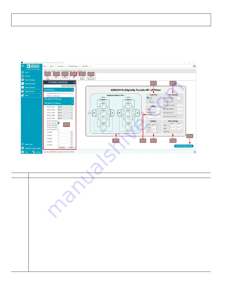
The full screen
ADMV8818
chip plugin with labels is shown in
Figure 7. The labels correspond to items listed in Table 1, which
describes the functionality of each section. For additional detailed
programming, refer to the
A
D
F
G
H
B
C
J1
J2
J3
J4
J5
J6
E
H
25839-
007
Figure 7.
ADMV8818
Chip Plugin with Labels
Table 1. ADMV8818 Chip Plugin Label Functions (See Figure 7)
Label
Function
A
Use the
CONFIGURATION
section to initialize the ADMV8818-EVALZ.
Load Settings from CSV
: click the
…
button to select which CSV file to load into the
CONFIGURATION
section.
Check to Load Settings
: once a file has been selected, select this check box to load the CSV file contents into the
CONFIGURATION
section. Note that a check mark does not appear when the check box is selected.
WR Mode HPF Settings
: select the input switch and high-pass filter (HPF) settings for SPI write mode.
WR Mode LPF Settings
: select the output switch and low-pass filter (LPF) settings for SPI write mode.
SFL Settings
: select the SPI fast latch (SFL) settings that are used when the chip is placed into the SPI fast latch mode. Note that
this function is not shown in Figure 7. Scroll down in the
CONFIGURATION
section to view this function.
Lookup Table 0 to 15
: define the configuration for lookup table (LUT)0 to LUT15. Note that these functions are not shown in
Figure 7. Scroll down in the
CONFIGURATION
section to view these functions.
Lookup Table 16 to 31
: define the configuration for LUT16 to LUT31.
Lookup Table 32 to 47
: define the configuration for LUT32 to LUT47.
Lookup Table 48 to 63
: define the configuration for LUT48 to LUT63.
Lookup Table 64 to 79
: define the configuration for LUT64 to LUT79.
Lookup Table 80 to 95
: define the configuration for LUT80 to LUT95.
Lookup Table 96 to 111
: define the configuration for LUT96 to LUT111.
Lookup Table 112 to 127
: define the configuration for LUT112 to LUT 127.
Summary
: click this button to review the settings for the initial setup.
Apply
: click this button to apply the settings to the chip. Note that clicking
Apply Changes
(J1) does not update the changes
in this section. Also, at startup, the main diagram user controls cannot be updated until the
Apply
button is clicked at least once.
Restore Software Defaults
: click this button to zero out the
CONFIGURATION
section prior to loading a different CSV file.


