Evaluation Board User Guide
UG-284
Rev. 0 | Page 3 of 24
SETTING UP THE BOARD—QUICK START
S
igma
S
tudio
SOFTWARE INSTALLATION
To install the SigmaStudio software, follow these steps:
1.
Open the provided .zip file and extract the files to your PC.
Alternatively, insert the SigmaStudio CD into the PC
optical drive and locate the SigmaStudio folder on the CD.
2.
If Microsoft .NET Framework Version 3.5 is not already
installed on the PC, install it by double-clicking
dotnetfx.exe
.
3.
Install SigmaStudio by double-clicking
setup.exe
and
following the prompts. A computer restart is not required.
HARDWARE SETUP, USBi
To set up the USBi hardware, follow these steps:
1.
Plug the USBi ribbon cable into Header J23.
2.
Connect the USB cable to your computer and to the USBi.
3.
When prompted for drivers, follow these steps:
a)
Select
Install from a list or a specific location
.
b)
Select
Search for the best driver in these locations
.
c)
Select the box for
Include this location in the search
.
The USBi driver is located in C:\Program Files\Analog
Devices Inc\Sigma Studio\USB drivers.
d)
Click
Next
.
e)
If prompted to choose a driver, select
CyUSB.sys
.
f)
If the PC is running Windows® XP and you receive the
message that the software has not passed Windows
logo testing, click
Continue Anyway
.
POWERING THE BOARD
1.
Plug the external dc power adapter into J34 to input 5 V dc
power to the board.
2.
Short Jumpers J40, J33, J31, and J32 to select the on-board
LDO-generated voltages that are connected to SPKVDD,
HPVDD, AVDD, and DVDD, respectively.
3.
Set Jumpers J43, J36, J39, J37, and J38 to select the required
voltage (1.8 V, 2.4 V, or 3.3 V) connected to each IOVDDx
(x = 1 to 5).
SETTING UP THE REGISTERS IN SigmaStudio
The codec is configured with SigmaStudio software. To set up
the registers in SigmaStudio, follow these steps:
1.
Create a new project. Select
New Project
under the
File
menu. The
Hardware Configuration
tab opens.
2.
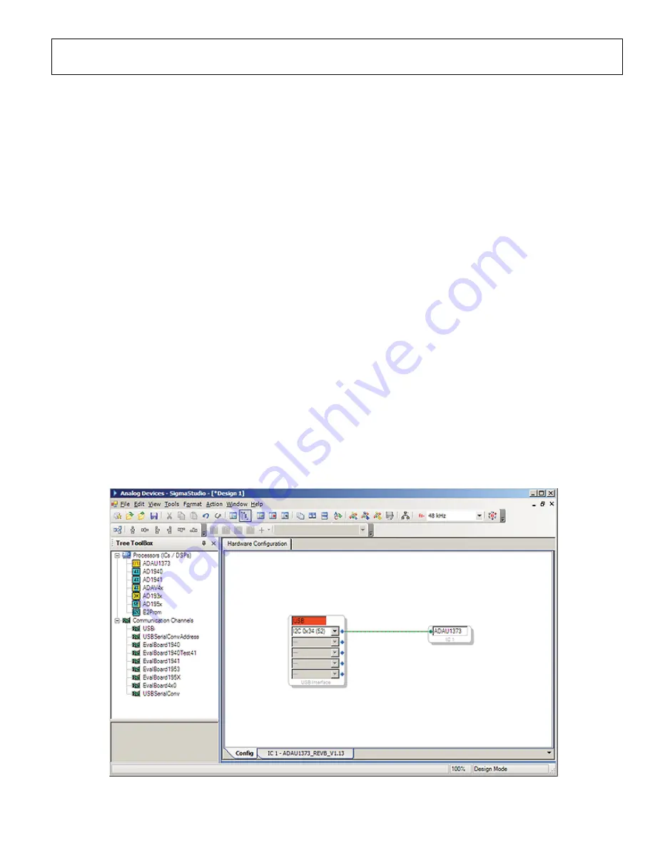
Click and drag an ADAU1373 cell and a USBi cell into the
blank work area.
3.
Connect the USBi cell to the ADAU1373 cell by clicking
and dragging from the top blue output pin of the USBi cell
to the green input pin of the ADAU1373 cell. The window
should now resemble Figure 1.
4.
In the
IC 1 - ADAU1373_REVB_V1.13
tab, configure the
ADAU1373 registers by clicking the intuitive graphic user
interface (GUI) elements in the
Input A
to
Input D
,
Analog Input Signal Routing
, and
Mic Bias Control
sections to set up the proper datapath (see Figure 2).
The SigmaStudio software includes help information. Press the
F1 key to open the help window.
0
989
9-
0
01
Figure 1. Hardware Configuration Tab—USBi Connection


