


AD5934
Rev. A | Page 13 of 40
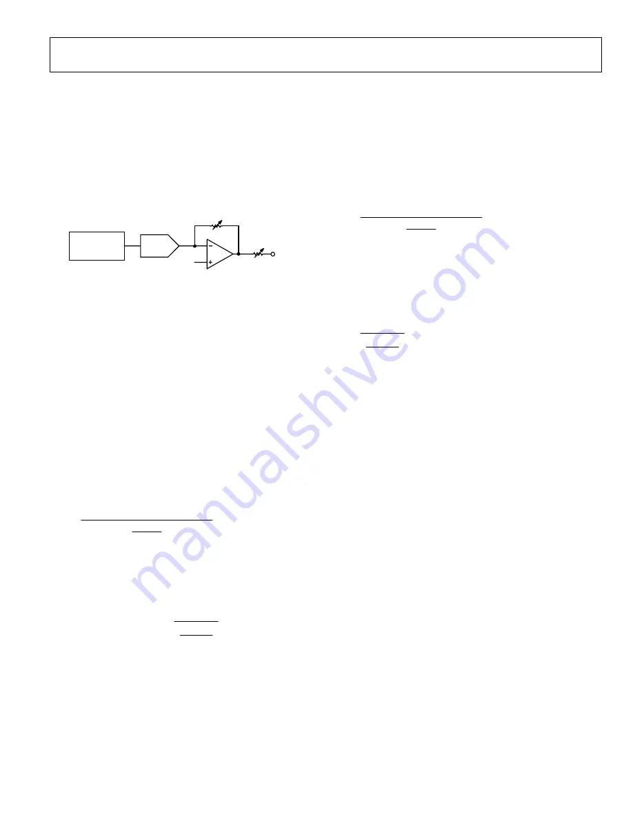
TRANSMIT STAGE
As shown in Figure 16, the transmit stage of the AD5934 is made
up of a 27-bit phase accumulator DDS core that provides the output
excitation signal at a particular frequency. The input to the phase
accumulator is taken from the contents of the start frequency register
(see Register Address 0x82, Register Address 0x83, and Register
Address 0x84). Although the phase accumulator offers 27 bits of
resolution, the start frequency register has the three most significant
bits (MSBs) set to 0 internally; therefore, the user has the ability to
program only the lower 24 bits of the start frequency register.
PHASE
ACCUMULATOR
(27 BITS)
VOUT
R
OUT
DAC
R(GAIN)
V
BIAS
0
532
5-
03
4
Figure 16. Transmit Stage
The AD5934 offers a frequency resolution programmable by the
user down to 0.1 Hz. The frequency resolution is programmed via
a 24-bit word loaded serially over the I
2
C interface to the frequency
increment register.
The frequency sweep is fully described by the programming of
three parameters: the start frequency, the frequency increment,
and the number of increments.
Start Frequency
This is a 24-bit word that is programmed to the on-board RAM
at Register Address 0x82, Register Address 0x83, and Register
Address 0x84 (see the Register Map section). The required code
loaded to the start frequency register is the result of the formula
shown in Equation 1, based on the master clock frequency and the
required start frequency output from the DDS.
27
2
16
×
⎟⎟
⎟
⎟
⎠
⎞
⎜⎜
⎜
⎜
⎝
⎛
=
MCLK
Frequency
Start
Output
Required
Code
Frequency
Start
(1)
For example, if the user requires the sweep to begin at 30 kHz and
has a 16 MHz clock signal connected to MCLK, the code that needs
to be programmed is given by
0x3D70A3
2
16
MHz
16
kHz
30
27
=
×
⎟⎟
⎟
⎟
⎟
⎠
⎞
⎜⎜
⎜
⎜
⎜
⎝
⎛
⎟
⎠
⎞
⎜
⎝
⎛
=
Code
Frequency
Start
The user programs the value of 0x3D to Register Address 0x82,
the value 0x70 to Register Address 0x83, and the value 0xA3 to
Register Address 0x84.
Frequency Increment
This is a 24-bit word that is programmed to the on-board RAM at
Register Address 0x85, Register Address 0x86, and Register Address
0x87 (see the Register Map section). The required code loaded to
the frequency increment register is the result of the formula shown in
Equation 2, based on the master clock frequency and the required
increment frequency output from the DDS.
27
2
16
×
⎟⎟
⎟
⎟
⎠
⎞
⎜⎜
⎜
⎜
⎝
⎛
=
MCLK
Increment
Frequency
Required
Code
Increment
Frequency
(2)
For example, if the user requires the sweep to have a resolution of
10 Hz and has a 16 MHz clock signal connected to MCLK, the code
that needs to be programmed is given by
0x00053E
16
MHz
16
Hz
10
≡
⎟⎟
⎟
⎟
⎟
⎠
⎞
⎜⎜
⎜
⎜
⎜
⎝
⎛
⎟
⎠
⎞
⎜
⎝
⎛
=
Code
Increment
Frequency
The user programs the value 0x00 to Register Address 0x85, the
value 0x05 to Register Address 0x86, and the value 0x3E to
Register Address 0x87.
Number of Increments
This is a 9-bit word that represents the number of frequency
points in the sweep. The number is programmed to the on-board
RAM at Register Address 0x88 and Register Address 0x89 (see the
Register Map section). The maximum number of points that can
be programmed is 511.
For example, if the sweep needs 150 points, the user programs
the value 0x00 to Register Address 0x88 and the value 0x96 to
Register Address 0x89.
Once the three parameter values are programmed, the sweep is
initiated by issuing a start frequency sweep command to the
control register at Register Address 0x80 and Register Address
0x81 (see the Register Map section). Bit D2 in the status register
(Register Address 0x8F) indicates the completion of the frequency
measurement for each sweep point. Incrementing to the next
frequency sweep point is under the control of the user. The measured
result is stored in the two register groups that follow: 0x94, 0x95
(real data) and 0x96, 0x97 (imaginary data) that should be read
before issuing an increment frequency command to the control
register to move to the next sweep point. There is the facility to
repeat the current frequency point measurement by issuing a
repeat frequency command to the control register. This has the
benefit of allowing the user to average successive readings. When
the frequency sweep has completed all frequency points, Bit D3 in
the status register is set, indicating the completion of the sweep.
Once this bit is set, further increments are disabled.
Содержание AD5934
Страница 35: ...AD5934 Rev A Page 35 of 40 SCHEMATICS 05325 144 Figure 40 EVAL AD5934EBZ USB Schematic ...
Страница 36: ...AD5934 Rev A Page 36 of 40 05325 145 Figure 41 EVAL AD5934EBZ Schematic ...
Страница 37: ...AD5934 Rev A Page 37 of 40 05325 146 Figure 42 Linear Regulator on EVAL AD5934EBZ ...
Страница 38: ...AD5934 Rev A Page 38 of 40 05325 147 Figure 43 Decoupling on the EVAL AD5934EBZ ...